FEATURES
• Vertical axis
with
wide
bandwidth
(20
MHz.
-3
dB) and high sensitivity (5 mV
/div.
1 div = 1
em).
•
AL
T and CHOP
operations
for
dual-trace
observation.
• The
time
base
switch
allows
changeover
between V (vertical) and H (horizontal)
of
VIDEO
sync
separator
circuit.
automatically
and
electronically.
• Distortion-free display
of
signals up to
20
MHz
on
the full area
of
CRT
screen.
• High sensitivity
CRT
(rectangular
with
internal
graticule)
with
excellent beam permeability has
sufficient
brightness
for
measurements
of
high-speed pulses
of
high frequencies.
• INT.
CH
1. CH2. LINE and EXT can be
individually synchronized for selection of desired
sync signals.
• The high voltage
power
for
CRT
as
well the
power for other circuits
is
fully stabilized
because of the use of
DC-
DC
converter. thus the
sensitivity and brightness are completely free
from effects
of
voltage variations.
•
At
AUTO position
of
TRIG LEVEL.
it
is
possible
to
check the brightness at no-signal
time
and
to
adjust triggering level
of
input waveforms.
• The adoption
of
ICs
throughout assures high
performance and improved reliability.
• X-Y operation is possible
with
CH2 amplifier
used
as
X axis. The horizontal axis sensitivity
is
as
high
as
5mV/div.
2
CONTENTS
Page
FEATURES ............................................................................... 2
SPECIFICATIONS...................................................................... 3
CONTROLS
ON
PANELS.......................................................... 5
Front Panel........................................................................... 6
Rear Panel
.. ..
..
..
.
.. .. .. .. ..
..
.. ..
.
..
..
..
..
..
..
.....
..
..
..
..
.....
.. .. ..
...
..
.
..
..
..
.. 8
OPERATION............................................................................. 8
Preliminary Operation............................................................ 8
Operating Procedures............................................................ 9
Measurement
of
Pulse Rising (Falling)
Time..........................
9
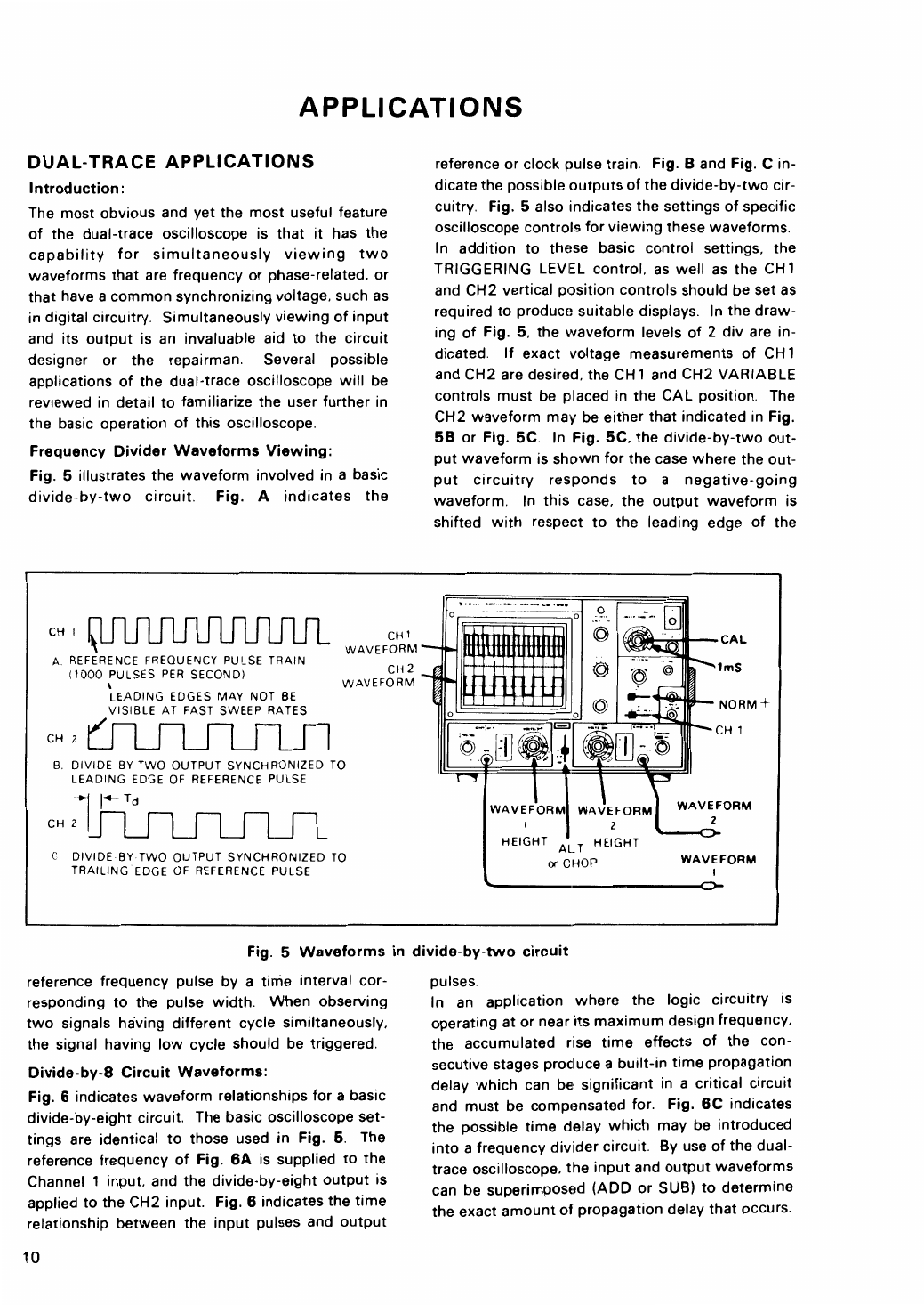
APPLICATIONS ......................................................·......·
..
···
..
·..
10
Dual-trace Applications ..............................···························
10
Single-channel Applications................................................... 19
FM
Receiver Adjustments .....................................................
22
X-Y Operation Applications ..................................
·.
···············
22
Amplifier Square Wave Test..................................................
24
PRECAUTIONS.........................................................................
29
MAINTENANCE AND
ADJUSTMENT........................................
29
Maintenance.........................................................................
29
Adjustment...........................................................................
30
SCHEMATIC DIAGRAM ............................................................
33