Vayyar V60G-HOME-I Manuale utente

V60G-HOME-I Module
User Manual
Revision 1.0.5
V60G-HOME-I User Guide
Vayyar Confidential
Page 2 of 19
Vayyar Imaging Ltd.
Web: https://vayyar.com
Notice
Copyright 2020 Vayyar Imaging Ltd. All rights reserved.
This document is the property of Vayyar and all materials and information contained herein are the confidential and proprietary
information of Vayyar and are protected by international copyright laws. The copyrights are owned by Vayyar or the original creator of the
material. The materials and information contained herein are provided to you for internal information purposes only, and no portion of
the materials and information herein may be copied, reproduced, distributed, transmitted, displayed, published, broadcasted or used in
any way whatsoever directly or indirectly without the prior written consent of Vayyar or in any case of third party materials, without that
third party's consent. This document shall be returned to Vayyar promptly upon request.
The materials and information contained herein are provided "AS IS" and Vayyar does not provide any warranties of any kind, whether
express or implied, including but not limited to implied warranties of merchantability, fitness for a particular purpose, and non-
infringement
Revision History
Revision
Date
Author
Description
1.0.1
February 2020
1.0.2
March 2020
1.0.3
August 2020
Canada
1.0.4
September 2020
Canada
1.0.5
October 2020

V60G-HOME-I User Guide
Vayyar Confidential
Page 3 of 19
Table of Contents
CHAPTER 1 INTRODUCTION .....................................................................................................6
1.1 Release Information Note.......................................................................................................6
1.2 Glossary...................................................................................................................................7
CHAPTER 2 SYSTEM OVERVIEW................................................................................................8
2.1 System Architecture................................................................................................................8
2.2 Hardware ..............................................................................................................................10
2.2.1 Sensor Unit Specification ..............................................................................................11
2.2.2 Digital Interface.............................................................................................................12
2.2.3 RF Interface - Antennas.................................................................................................13
2.2.4 Electrical Specifications.................................................................................................13
2.2.5 Antenna and RF Characteristics....................................................................................14
2.3 Software................................................................................................................................15
CHAPTER 3 REGULATORY SECTION......................................................................................... 16
3.1 Compliance ...........................................................................................................................16
3.1.1 FCC ................................................................................................................................16
3.1.2 IC ...................................................................................................................................17
3.2 Instructions for the Integrator..............................................................................................18
3.2.1 OEM Integrators Notices...............................................................................................18
3.2.2 End Product Labeling ....................................................................................................18
3.2.3 OEM Manual Information that Must be Included ........................................................18
3.2.4 RF Exposure Guidance...................................................................................................19

V60G-HOME-I User Guide
Vayyar Confidential
Page 4 of 19
List of Figures
Figure 1: V60G-HOME-I “EVK” System Architecture...............................................................................8
Figure 2: V60G-HOME-I “Embedded” System Architecture ...................................................................9
Figure 3: High-Level Block Diagram –USB-based system.....................................................................10
Figure 4: vStraw_CTPB4 Connectivity...................................................................................................12
Figure 5: vBLU_OK _CTPB4 connector..................................................................................................13
Figure 6: Antenna Positions and Numbering........................................................................................13
Figure 7: V60G-HOME-I Antenna Pattern.............................................................................................14
Figure 8: Processing Flow......................................................................................................................15

V60G-HOME-I User Guide
Vayyar Confidential
Page 5 of 19
List of Tables
Table 1: Glossary.....................................................................................................................................7
Table 2: Sensor Unit Specification ........................................................................................................11
Table 3: Sensor Unit Electrical Specification.........................................................................................14
Table 4: Antenna and RF Characteristics ..............................................................................................14

V60G-HOME-I User Guide
Vayyar Confidential
Page 6 of 19
Chapter 1
Introduction
This guide provides information on the installation and operation of the Vayyar V60G-HOME-I
modules.
V60G-HOME-I is a family of multi-antenna millimeter-wave modules operating at 60GHz bands, based
on the company’s VYYR7201 RF SoC, generating a 3D image of the sensor’s vicinity by transmitting and
receiving mm-wave signals from multiple antennas (MIMO), used as a fixed field disturbance sensor or
a short-range device for interactive motion sensing.
Models pertaining to the V60G-HOME-I family are intended to be integrated with an additional host,
either a PC-host operating the device through a USB interface, or a microcontroller-unit (MCU) for
integrated and embedded products.
The sensor detects objects in a defined arena and provides 3D-data of the targets to the host, such as:
position within the arena, class or posture; a raw 3D image (point-cloud for example).
Typical applications for the device can be touchless input device (e.g. gesture-recognition interface),
in-room people detection and monitoring for improving comfort and energy-utilization optimization
(e.g. HVAC operation and airflow optimization), detection of abnormal conditions such as fall of elderly
people and apnea in adults and babies, and in-cabin monitoring for detection of infants left in car.
The models participating in the V60G-HOME-I family (and certified under modular-approval) include,
but not limited to: vStraw_CTPB4_I, vBLU_OK_CTPB4, vBLU_MW_CTPB4.
1.1 Release Information Note
Software capabilities, algorithmic capabilities and different features are under continuous
development and improvement.
This document provides basic description of the system and it is operated. For more details –contact
Vayyar LTD through –www.vayyar.com.
V60G-HOME-I User Guide
Vayyar Confidential
Page 7 of 19
1.2 Glossary
Table 1: Glossary
Term
Definition
AC
Alternating Current
API
Application Programming Interface
DC
Direct Current
DLL
Dynamic Link Library
EVK
Evaluation Kit
GUI
Graphical User Interface
IP
Internet Protocol. An IP address is a numerical identifier assigned to a computing device or
node in a TCP/IP network. The address is used to locate and identify the node in
communications with other nodes on the network.
MCU
Micro-Controller Unit
PCB
Printed Circuit Board
RF
Radio Frequency
SoC
System-on-chip
V60G-HOME-I User Guide
Vayyar Confidential
Page 8 of 19
Chapter 2
System Overview
2.1 System Architecture
The V60G-HOME-I system may be operating with a host-PC and dedicated control and imaging SW
and GUI (for example an “EVK” architecture), or by running an imaging engine on a dedicated DSP
embedded into the proprietary VYYR7201_CTPB4 chips and using a dedicated API to extract the
processing outputs (“embedded architecture”), or any combination of the two.
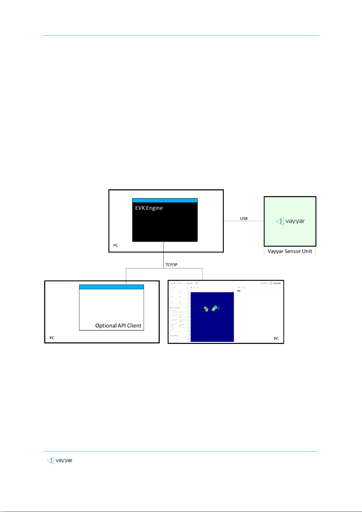
An “EVK” architecture and connectivity scheme is illustrated in the figure below.
Figure 1: V60G-HOME-I “EVK” System Architecture
The “EVK” V60G-HOME-I system is comprised of the following components:
The V60G-HOME-I RF Sensor module.
The EVK Engine. Host software that performs signal processing functions. The software
runs in a command window in a PC, which is connected to the V60G-HOME-I Sensor via a
USB cable.
V60G-HOME-I User Guide
Vayyar Confidential
Page 9 of 19
Web GUI. User-interface client software that communicates with the EVK Engine via a
TCP/IP connection.
API Client. Optional, customer-developed software that communicates with the EVK
Engine via a TCP/IP connection.
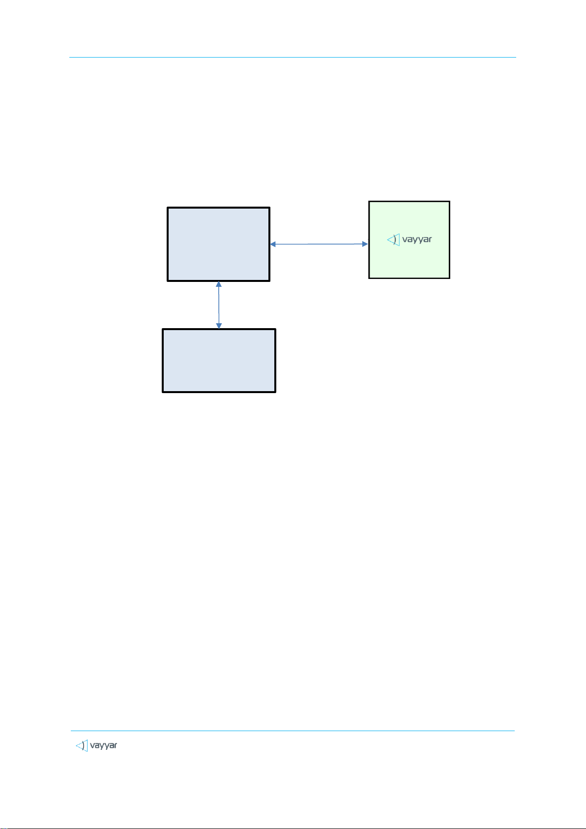
A typical “Embedded” architecture is depicted in the following figure:
Figure 2: V60G-HOME-I “Embedded” System Architecture
Examples of used controllers may include EPS32, Raspberry-Pi CPU, etc.
Vayyar sensor module
Host Controller /
CPU
[Application]
SPI , USB
Central processing
unit \ server \ cloud
LAN \ WLAN \ Cellular
V60G-HOME-I User Guide
Vayyar Confidential
Page 10 of 19
2.2 Hardware
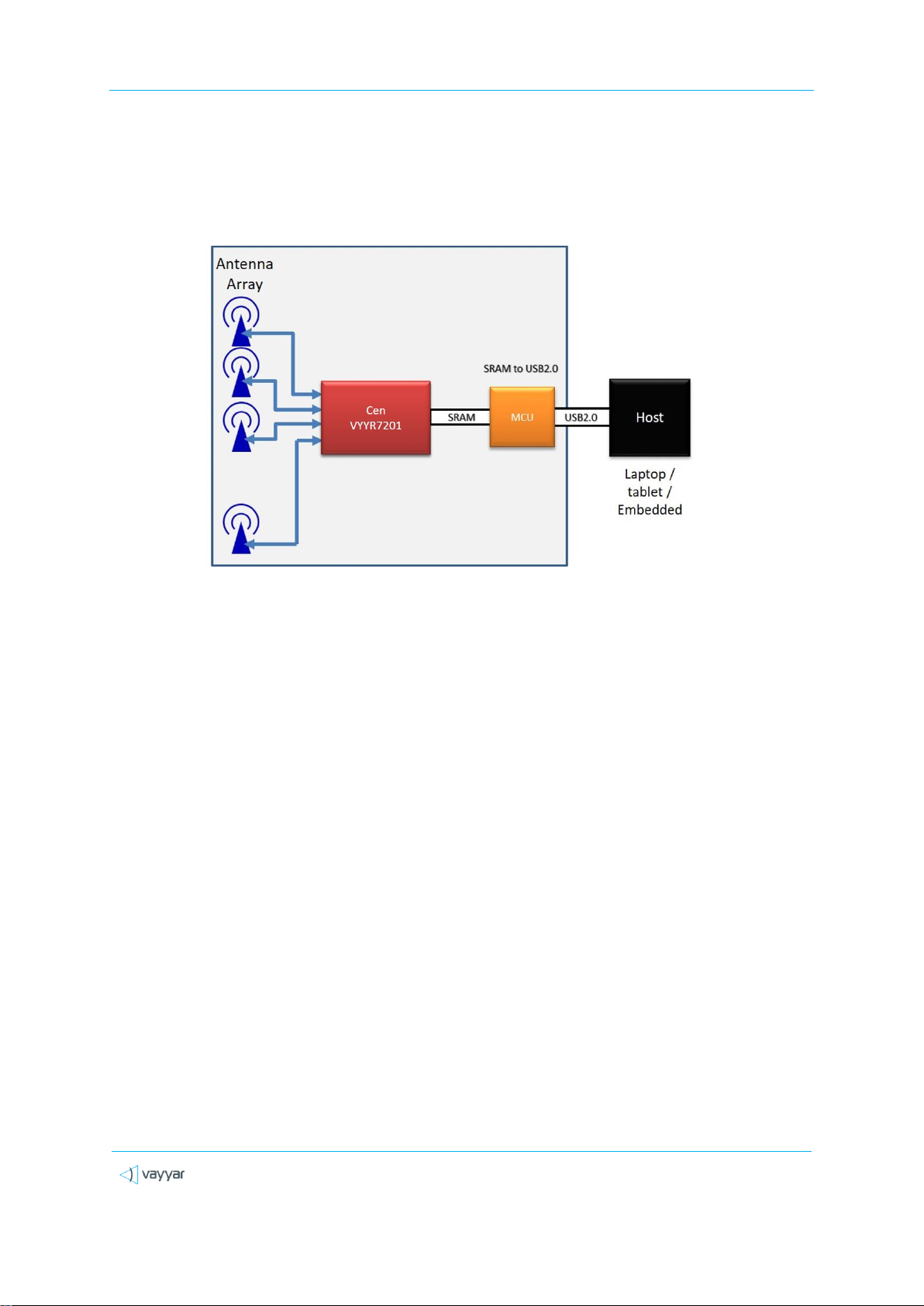
The figure below presents a high-level block diagram of the PCB that houses the USB-based sensor
unit:
Figure 3: High-Level Block Diagram –USB-based system
An SPI-based module is similar, excluding the USB-related components. The following components
are embedded in the sensor unit PCB:
Vayyar VYYR7201-B4 system-on-chip (SoC).
46 embedded Tx/Rx linear polarized PCB embedded, wide-band antennas.
A Crystal used as a clocking source for the Cypress MCU.
A TCXO (Temperature Compensated Crystal Oscillator) used as a clocking source for the
VYYR7201-B4 SoC.
Power supply system supporting 3.3V, 2.5V, 1.27V and 1.2V DC/DC converters.
For USB-based models - a digital interface that communicates with a host PC via a USB-2.0
connection. The interface is implemented using on-board Cypress micro-controller unit
(MCU).
For SPI-based models –the interface is communicating directly with VYYR7201- B4 SoC.
Questo manuale è adatto per i seguenti modelli
1
Indice
Manuali Unità di controllo popolari di altre marche

Festo
Festo Compact Performance CP-FB6-E Manuale elenco delle parti

Elo TouchSystems
Elo TouchSystems DMS-SA19P-EXTME Manuale utente

JS Automation
JS Automation MPC3034A Manuale utente

JAUDT
JAUDT SW GII 6406 Series Guida rapida

Spektrum
Spektrum Air Module System Manuale utente

BOC Edwards
BOC Edwards Q Series Manuale utente


