
ABB WaterMaster Manuale utente

—
ABB MEASUREMENT & ANALYTICS | USER GUIDE | IM/WM REV. M
WaterMaster
Electromagnetic flowmeter
Measurement made easy
—
WaterMaster
flowmeter

For more information
Further publications for the WaterMaster
electromagnetic flowmeter are available for free
download from:
www.abb.com/measurement
or by scanning this code:
Search for or click on
Data Sheet
WaterMaster | Electromagnetic flowmeter
DS/WM-EN
Programming Guide
WaterMaster | Electromagnetic flowmeter
IM/WMP
User Guide Supplement – PROFIBUS RS485 Physical Layer (FEX100-DP)
WaterMaster | Electromagnetic flowmeter
IM/WMPBS-EN
User Guide Supplement – PROFIBUS FEX100-DP Parameter Tables
WaterMaster | Electromagnetic flowmeter
IM/WMPBST-EN
Setup Guide
VeriMaster | Software tools
IM/WM/VM

WaterMaster
Electromagnetic flowmeter
IM/WM–EN Rev. M 1
1 Safety ............................................................................................................................................... 2
1.1 Electrical Safety ............................................................................................................................................. 2
1.2 Symbols ........................................................................................................................................................ 2
1.3 Health & Safety ............................................................................................................................................. 3
2 Introduction ...................................................................................................................................... 4
2.1 Quality Control .............................................................................................................................................. 4
3 Mechanical Installation .................................................................................................................... 5
3.1 Unpacking .................................................................................................................................................... 5
3.2 Installation Conditions ................................................................................................................................... 5
3.3 Dimensions ................................................................................................................................................. 10
3.3.1 Transmitter Dimensions ................................................................................................................ 10
3.3.2 Sensor Dimensions ....................................................................................................................... 11
4 Electrical Installation ..................................................................................................................... 15
4.1 Grounding ................................................................................................................................................... 15
4.2 Remote Transmitter / Sensor Arrangement ................................................................................................. 17
4.3 Transmitter Terminal Connections ............................................................................................................... 18
4.4 Cable Preparation (Remote Systems Only) .................................................................................................. 20
4.5 Transmitter / Sensor Cable Connections ..................................................................................................... 20
4.5.1 Sensor Cable Terminal Connections and Recommended Cable Lengths ...................................... 21
4.5.2 Environmental Protection .............................................................................................................. 22
4.6 Output Connections .................................................................................................................................... 23
4.6.1 Frequency Outputs ....................................................................................................................... 23
4.6.2 Alarm Outputs .............................................................................................................................. 24
4.6.3 Current Output (4 to 20 mA) – HART (FEX100) Variant .................................................................. 24
4.6.4 RS485 Communications – PROFIBUS (FEX100–DP) and MODBUS (FEX100–MB) Variants .......... 25
4.6.5 Test Point Access ......................................................................................................................... 25
4.7 Power Supply Connections ......................................................................................................................... 26
4.7.1 AC Power Supply ......................................................................................................................... 26
4.7.2 DC (and Low Voltage AC) Power Supply ......................................................................................27
4.7.3 Configuration DIP Switches .......................................................................................................... 28
4.8 Refitting the Cartridge and Cover ................................................................................................................ 28
5 Start-up and Operation ................................................................................................................. 30
5.1 Navigating the Menus and Parameters ........................................................................................................ 30
5.2 Start-up Screens ......................................................................................................................................... 31
5.3 Security Levels and Password Access ........................................................................................................ 33
5.3.1 Default Passwords ....................................................................................................................... 34
5.3.2 Entering Passwords ...................................................................................................................... 34
5.4 Easy Setup ................................................................................................................................................. 35
6 WaterMaster Flow Performance ................................................................................................... 36
6.1 WaterMaster flow performance – m3/h ....................................................................................................... 36
6.2 WaterMaster flow performance – gal/min .................................................................................................... 38
7 Specification – Sensor ................................................................................................................... 39
8 Specification – Transmitter ........................................................................................................... 42
Notes .................................................................................................................................................... 44
WaterMaster
Electromagnetic flowmeter 1 Safety
2IM/WM–EN Rev. M
1 Safety
Information in this manual is intended only to assist our customers in the efficient operation of our
equipment. Use of this manual for any other purpose is specifically prohibited and its contents are not to be
reproduced in full or part without prior approval of the Technical Publications Department.
1.1 Electrical Safety
This equipment complies with the requirements of CEI/IEC 61010-1:2001-2 'Safety Requirements for
Electrical Equipment for Measurement, Control and Laboratory Use' and complies with NIST and OSHA.
If the equipment is used in a manner NOT specified by the Company, the protection provided by the
equipment may be impaired.
1.2 Symbols
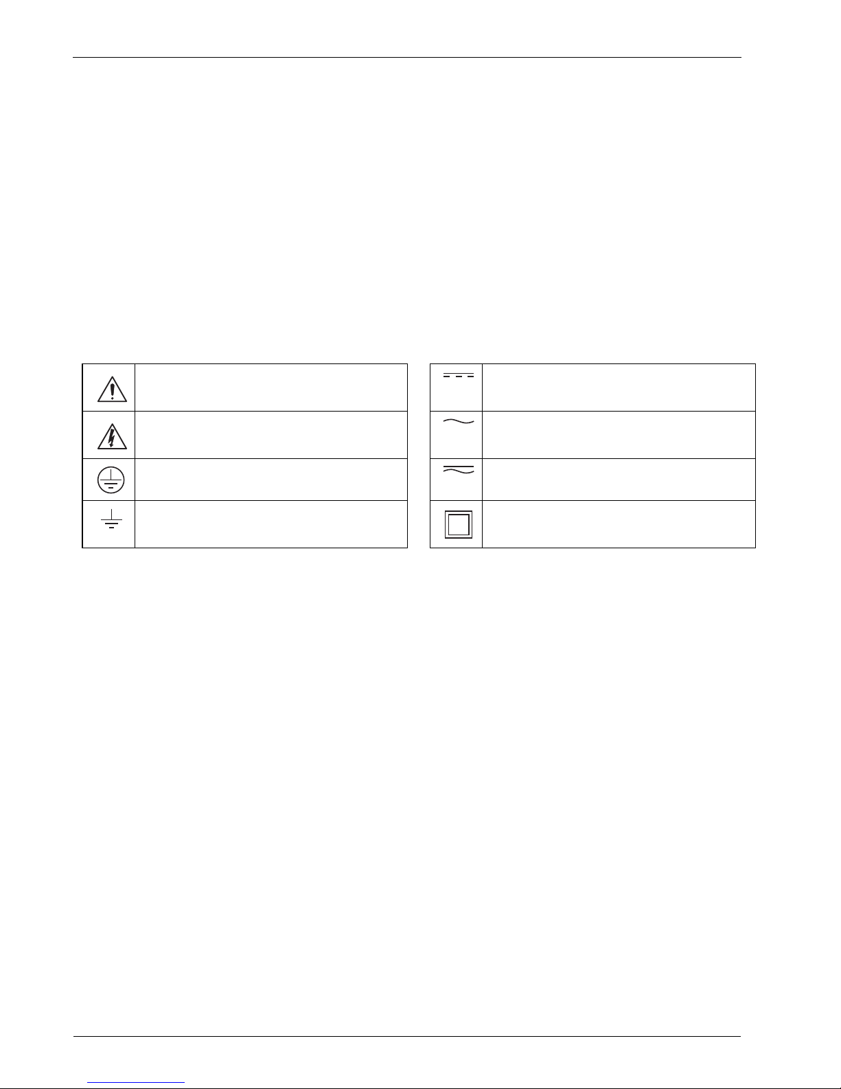
One or more of the following symbols may appear on the equipment labelling:
Warning – Refer to the manual for instructions Direct current supply only
Caution – Risk of electric shock Alternating current supply only
Protective earth (ground) terminal Both direct and alternating current supply
Earth (ground) terminal The equipment is protected
through double insulation

WaterMaster
Electromagnetic flowmeter 1 Safety
IM/WM–EN Rev. M 3
1.3 Health & Safety
To ensure that our products are safe and without risk to health, the following points must be noted:
The safety requirements of this equipment, any associated equipment and the local
environment must be taken into consideration during installation.
Install and use this equipment and any associated equipment in accordance with the relevant
national and local standards.
The relevant sections of these instructions must be read carefully before proceeding.
Warning labels on containers and packages must be observed.
Installation, operation, maintenance and servicing must only be carried out by suitably trained
personnel and in accordance with the information given.
Normal safety precautions must be taken to avoid the possibility of an accident occurring when
operating in conditions of high pressure and / or temperature.
Chemicals must be stored away from heat, protected from temperature extremes and powders
kept dry. Normal safe handling procedures must be used.
When disposing of chemicals ensure that no two chemicals are mixed.
Product liability – advice and assistance provided without charge is given in good faith but
without liability.
Safety advice concerning the use of the equipment described in this manual or any relevant hazard
data sheets (where applicable) may be obtained from the Company address on the back cover,
together with servicing and spares information.

WaterMaster
Electromagnetic flowmeter 2 Introduction
4IM/WM–EN Rev. M
2 Introduction
WaterMaster™ is a range of high performance electromagnetic flowmeters for the measurement of
electrically conductive fluids and systems are normally supplied factory-configured and calibrated.
This User Guide provides installation, connection, security, start-up and basic setup details. For
programming and configuration information refer to the Programming Guide – IM/WMP.
This User Guide should be used in conjunction with the following publications:
Programming Guide – IM/WMP
For Profibus DP variants (FEX100-DP)
User Guide Supplement, PROFIBUS RS485 Physical Layer (FEX100-DP) – IM/WMPBS–EN
User Guide Supplement, PROFIBUS FEX100-DP Parameter Tables – IM/WMPBST–EN
For Modbus variants (FEX100-MB)
User Guide Supplement, MODBUS RS485 Physical Layer COI/FEX100/MOD–EN
User Guide Supplement, MODBUS Tables COI/FEX100/MOD/TBL–EN
2.1 Quality Control
The UKAS Calibration Laboratory No. 0255 is just one of the ten flow calibration plants operated by the
Company and is indicative of our dedication to quality and accuracy.
Warning.
System configuration must be carried out only by users or personnel with approved access rights
(user privileges).
Read all relevant sections of this guide before configuring the system or modifying system
parameters.
Install and use associated equipment in accordance with the relevant national and local
standards.
Fig. 2.1 UKAS Calibration Laboratory No. 0255
0255
WaterMaster
Electromagnetic flowmeter 3 Mechanical Installation
IM/WM–EN Rev. M 5
3 Mechanical Installation
3.1 Unpacking
3.2 Installation Conditions
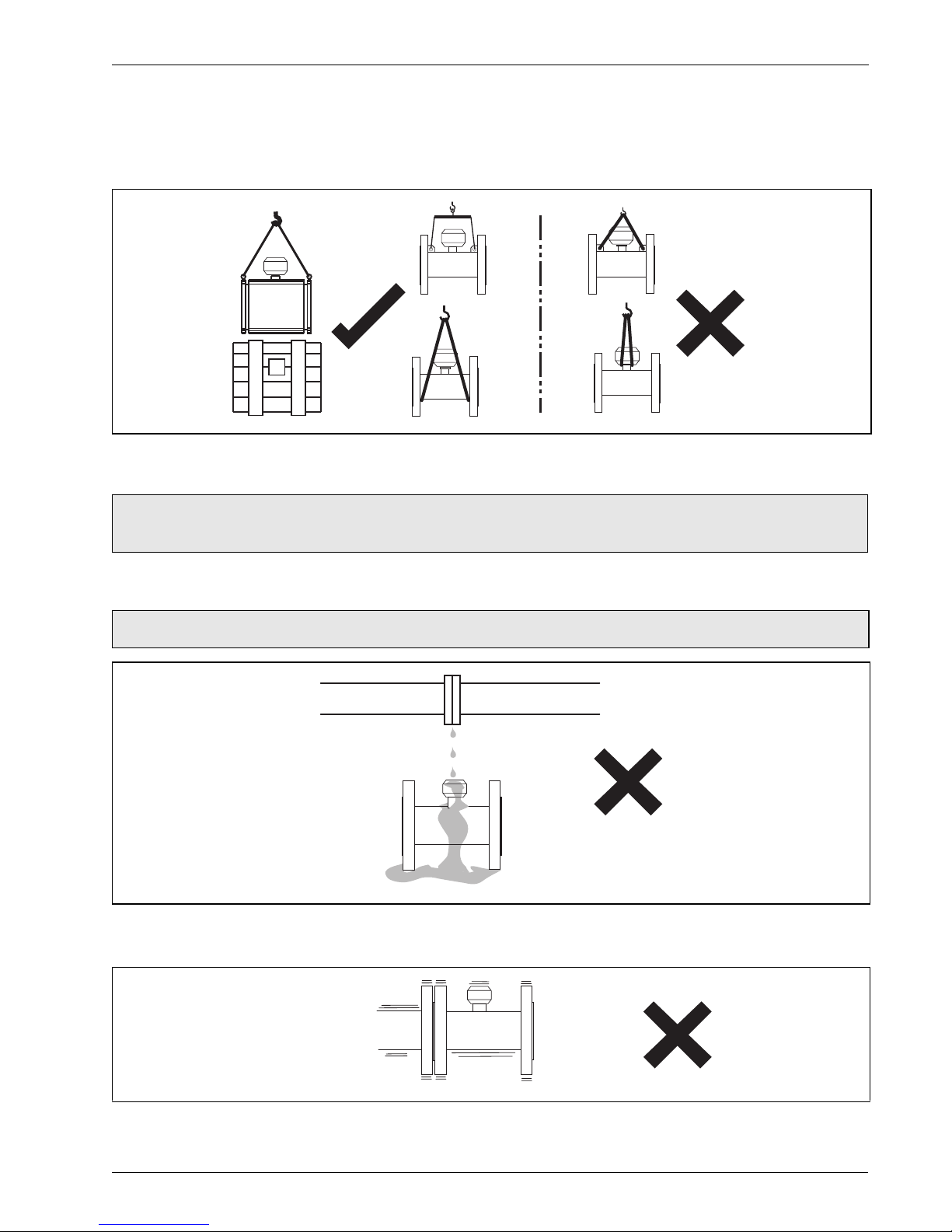
Fig. 3.1 Unpacking
Caution. Visually inspect equipment for damage before installing. Do not install damaged or faulty
equipment.
Caution. Do NOT exceed the maximum working pressure marked on the equipment.
Fig. 3.2 Spillage
Fig. 3.3 Vibration
Sling Angle <90°
Vibration Limit
5 Hz to 150 Hz

WaterMaster
Electromagnetic flowmeter 3 Mechanical Installation
6IM/WM–EN Rev. M
Fig. 3.4 Localized Heat
Fig. 3.5 Siting
Fig. 3.6 Straight Pipe Requirements
Fig. 3.7 Fluid Level
Allow room to read display
Min.
Min.
>5 x Pipe Dia.0 x Pipe Dia.
Flow Direction

WaterMaster
Electromagnetic flowmeter 3 Mechanical Installation
IM/WM–EN Rev. M 7
Fig. 3.8 Within Temperature Limits
Fig. 3.9 Shade
Fig. 3.10 Above Ground
60 °C (140 °F) Max.
–20 °C
(–4 °F)
Min.
Supports

WaterMaster
Electromagnetic flowmeter 3 Mechanical Installation
8IM/WM–EN Rev. M
Fig. 3.11 Temperature Difference
Fig. 3.12 Within Environmental Rating
Fig. 3.13 Underground
Note. For further details when burying flow sensors contact the ABB Service Organization.
IP67 (NEMA 4X)IP68 (NEMA 6)
Transmitter Submersion:
1 m (3.3 ft) <12 hours
Accrued time
Sensor Submersion: Continuous
Protection Plate
Recommended
Backfill
Altri manuali per WaterMaster
2
Indice
Altri manuali ABB Strumento di misura

ABB
ABB COPA-XM 3000 Series Manuale utente

ABB
ABB JDF300 Manuale utente

ABB
ABB COMMANDER 1911 Manuale utente

ABB
ABB NGC8206 Manuale utente

ABB
ABB RES670 2.1 Guida rapida

ABB
ABB FSM4000-SE41F Manuale utente

ABB
ABB EL6010 Manuale utente

ABB
ABB FV4000-VT4 Manuale utente

ABB
ABB SACE PR010/T Manuale utente

ABB
ABB CoreSense M10 Manuale utente

ABB
ABB ICOS GLA431-MCIA Manuale utente

ABB
ABB 8002 Manuale utente

ABB
ABB AX410 Manuale utente

ABB
ABB IM/SM3000 Manuale utente

ABB
ABB Aztec 600 Manuale utente

ABB
ABB FAM3200 Series Manuale di installazione e funzionamento

ABB
ABB B23 Manuale utente

ABB
ABB ADS420 Manuale utente

ABB
ABB FMT200-ECO2 Manuale utente

ABB
ABB AK101 Manuale utente


