Alcor System CSSMS Manuale utente

© ALCOR-SYSTEM 1
Continuous Solar Seeing Measurement
System
CSSMS
Installation and user manual
April 12th, 2021

© ALCOR-SYSTEM 2
Table of Contents
1 CSSMS installation ..................................................................................................................................................... 3
1.1 Control Box installation ..................................................................................................................................... 3
1.2 Sensor installation ............................................................................................................................................. 8
2 Software .................................................................................................................................................................. 10
2.1 System requirement and operating system .................................................................................................... 10
2.2 installation software ....................................................................................................................................... 11
2.3 Software User Interface .................................................................................................................................. 15
2.3.1 Recorded data ......................................................................................................................................... 19
3 System maintenance ............................................................................................................................................... 20
4 Trouble shooting ..................................................................................................................................................... 21
4.1 System does not deliver any measurements .................................................................................................. 21
5 Product terms of use ............................................................................................................................................... 21
© ALCOR-SYSTEM 3
1 CSSMS installation
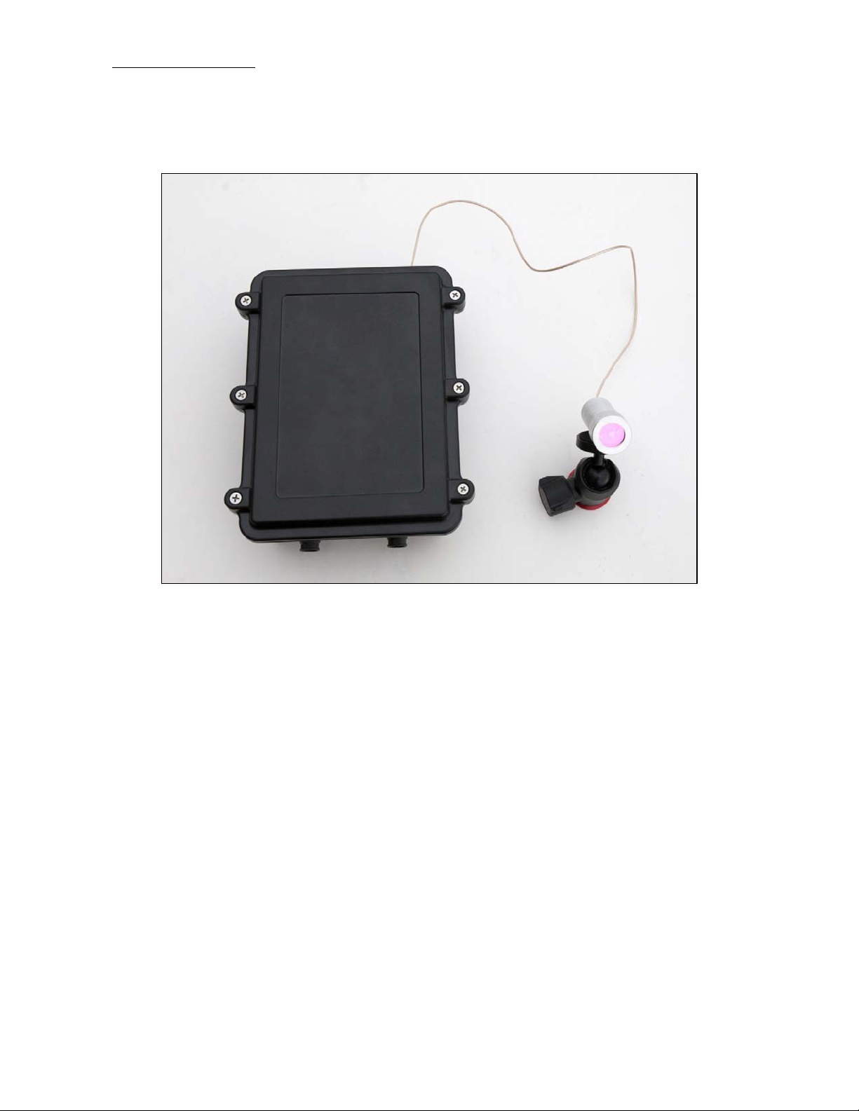
The system is made of two parts, a control box and a sensor mounted to a ball support that allows any
orientations. The sensor cannot be detached from the control box, and in located 50 cm apart.
Fig. 1 Complete system without cables to computer and power supply, left main control box and right the sensor
made of photodiode and green filter.
The system works outdoor, it is weather-tight and can withstand wind, rain and snow. it will prevent all
intrusion of insects, even the smallest one. Nevertheless, the system is not submersible into water.
The base plate to attach the box and the sensor is not provided.
1.1 Control Box installation
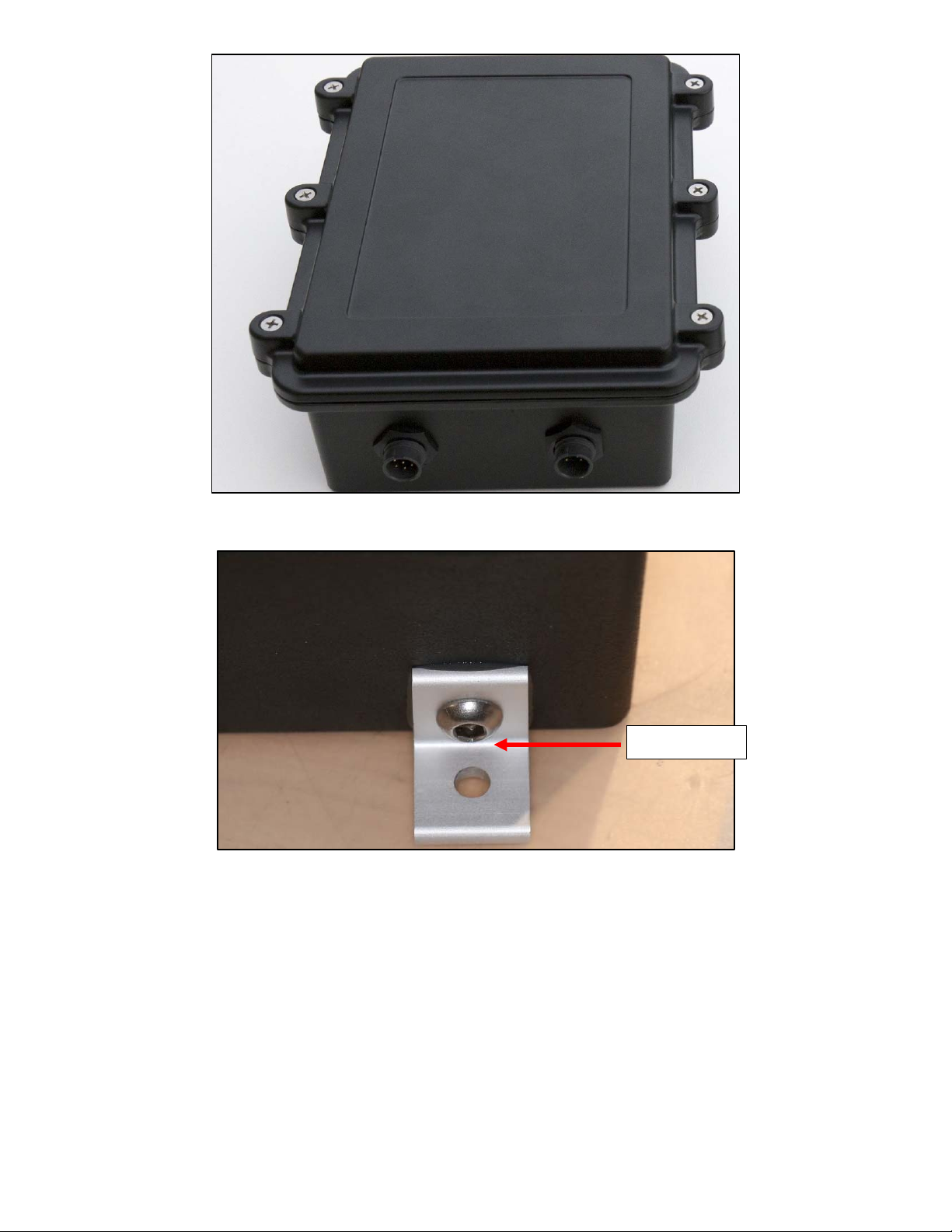
The box has two fixing brackets on the side which allows to fix the system on a wall or other robust surface.
It is also possible to fix it on a vertical surface, in that case have the 2 connectors downward. Bracket hole
diameter are 6mm or ¼ ’’. Attachment screws are not provided because their types are defined accordingly
to the material where the box will be located.
© ALCOR-SYSTEM 4
Fig. 2 Control box
Fig. 3 Fixing brackets
Take care of the coaxial cable at the output of the box, it is short and fragile. Do not stretch it to the
maximum length or/and avoid to twist it.
Connector keying and different number of pins are preventing connection errors. However, user must look at
the number of connector pins at the end of the cord before connecting the camera, in order to avoid forcing
the pins and damage the camera connector.
∅6 mm
/
¼’’

© ALCOR-SYSTEM 5
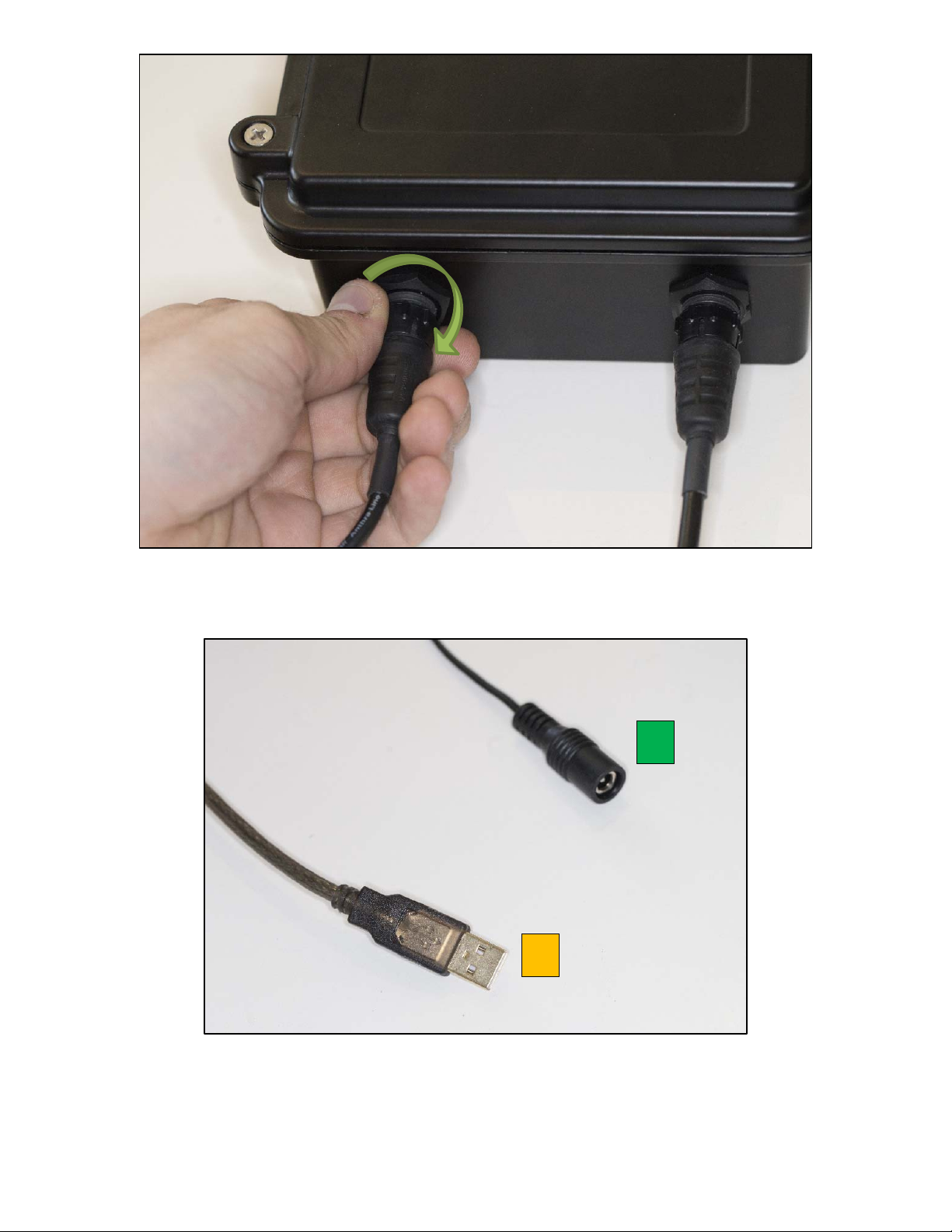
Fig. 4
Control box connectors side
Connector
Role Gender (camera side)
#1
USB connector Male 5 pins
#2
Power connector Male 2 pins
USB connector (#1)
This is tied up to a 6 pins connector. Please connect the CSSM first and then connect to PC second. The cable
that goes to the PC is 20m length.
Power connector (#2)
This is tied up to a 2 pins connector. This is 24V power supply. This is a 20m cable.
The 2 waterproof connectors (USB connector and Power connector) connect as follows:
Identify the number of connector pins of the system, its type (male / female)
Identify the number of pins of the connector cord and match.
Identify the key pin inside the camera connector and the key at the connector cord side.
Apply a rectilinear motion. If insertion force strength persists, please repeat steps for
locating the pin number and key. Excessive force applied to connector can cause
the
destruction of the connector or a bad connection can damage the system. In case of
damage due to trials to attach cable to the wrong connector kind, warranty could be
canceled.

© ALCOR-SYSTEM 6
Fig. 5
Connectors’ definition
Turn the connector a little bit, when you fell the two parts of the connector are facing, then the connector
can be pushed into its counterpart. You should never force it; it should be gentle!
Fig. 6
Connector attachment step #1: go straight with proper key orientation
When the connector is correctly pushed you can turn the locking ring clockwise to attach it.
© ALCOR-SYSTEM 7
Fig. 7 Connector attachment step #2: rotate clockwise to have to lock the ring to prevent the cable from detaching
Fig. 8 Connectors opposite side from box
1
2

© ALCOR-SYSTEM 8
When the connector is correctly pushed you can turn the locking ring clockwise to attach it. On the other
side connector #2 goes to the 24V/1.5A power supply, and connector #1 goes to any USB port of your PC.
This is an USB 2.0 Link.
1.2 Sensor installation
The sensor is a photodiode placed into a waterproof casing in the backside of a special green filter (see
below filter transmission) it peaks at 550 nm.
The sensor is placed on a mount head ball that can allow any angle of sight. This angle of sight is set once for
all, depending on the latitude of the place and north/south directions.
Fig. 9 Green filter transmission plot
It should face the SUN, more particularly the South (for northern hemisphere operation) or the North (for
southern hemisphere operation) direction. The angle of the sensor with respect to horizontal plane is equal
to 90° minus Latitude place angle.
For instance, if latitude is 30° North, it should be put aiming South in azimuth and at 60° angle of elevation
from the horizontal plane.
Positioning accuracy is not critical, and +/- 5° error can be accepted.
Ensure that no building will hide the Sun during its path from sunrise to sunset. Also think, that over the
course of the year the Sun position is changing, extreme values are from winter solstice to summer solstice.

© ALCOR-SYSTEM 9
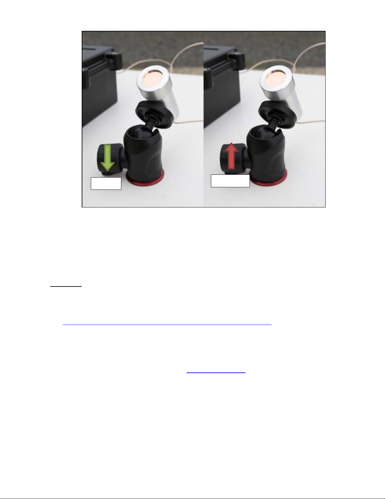
The base of the ball support has a female thread 3/8’’ 16 TPI UNC thread, allowing to attach it in a
permanent position nearby the control box. Please, be sure both axis (azimuth and elevation) are tightened
very firmly, so that it does not move over the course of the time because of the wind or the effect of the
rain.
Fig. 10 Photodiode/sensor angle azimuth is set to north (or south) axis and elevation to 90° - latitude of the observing
place.
© ALCOR-SYSTEM 10
Fig. 11 Locking / Unlocking process of the elevation angle ball
System installation is complete and ready to go.
Important: the system works daytime, but does not provide any seeing data when Sun is hidden by clouds.
2 Software
Latest product software can be found in our web site:
http://www.alcor-system.com/common/CSSMS/software/CSSMS_Installer.exe
2.1 System requirement and operating system
Hardware requirement (Minimum) for CSSMS V1
PC with AMD or Intel CPU, (with passmark index above 2000)
o Intel Core i3-4012Y @ 1.50GHz (passmark index : 2000)
2 GB Memory
50 GB hard disk. Software requires 20 MB for installation, but storage must be granted for images.
Operating system requirement
Windows 10, 8, and 7. 32- or 64-bits OS.
May work with windows XP, but no support will be provided for this deprecated OS.
LOCK UNLOCK
Indice


