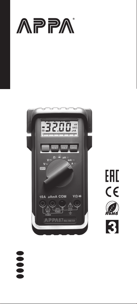
APPA 67 Manuale utente

RU
EN
TC
SC
JP
Pocket-Size Multimeter
Мультиметр компактный
User Manual / 使用說明書 / 使用说明书
ユーザーマニュアル
Руководство пользователя
67
LIMITE D
WARRAN TY
YEAR S

Read First
!
!Safety Information
Warning (Identify hazardous conditions and actions
that could cause BODILY HARM or DEATH)
• General (Including the request from EN61010-1)
• If the equipment is used in a manner not specified by the
manufacturer, the protection provided by the
equipment may be impaired.
• Always use proper terminals, switch position, and range
for measurements.
• To reduce the risk of fire or electric shock, do not use this
product around explosive gas or vapor.
• Verify the Meter operation by measuring a known
voltage. If in doubt, have the Meter serviced.
• Do not apply more than the rated voltage, as marked on
Meter, between terminals or between any terminal and
earth ground.
• To avoid false readings that can lead to electric shock
and injury, replace battery as soon as low battery
indicator appears.
• Avoid working alone so assistance can be rendered.
• Do not use the Tester if the Tester is not operating
properly or if it is wet.
• Individual protective device must be used if hazardous
live parts in the installation where the measurement is to
be carried out could be accessible.
• When using test leads or probes, keep your fingers
behind the finger guards.
• Do not use test leads or the Tester if they look damaged.
• Remove test lead from Meter before opening the battery
door or Meter case.
• Only replace the blown fuse with the proper rating as
specified in this manual.
• Do not attempt a current measurement when the open
voltage is above the fuse protection rating. Suspected
open voltage can be checked with voltage function.
67 EN
1

• Never attempt a voltage measurement with the test lead
inserted into the A input terminal
• Use caution with voltages above 30 Vac rms, 42 Vac
peak, or 60 Vdc. These voltages pose a shock hazard.
• DO NOT USE the test leads above maximum ratings of
CAT. environment, voltage and current, that are indicated
on the probe and the probe tip guard cap.
• DO NOT USE the test leads without the probe tip guard
cap in CAT III and CAT IV environments.
• Probe assemblies to be used for MAINS measurements
shall be RATED as appropriate for MEASUREMENT
CATEGORY III or IV according to IEC 61010-031 and
shall have a voltage RATING of at least the voltage of
the circuit to be measured.
• Disconnect circuit power and discharge all high-voltage
capacitors before testing resistance, continuity, diodes.
Caution (Identify conditions and actions that could
cause DAMAGE the meter or equipment under test)
General
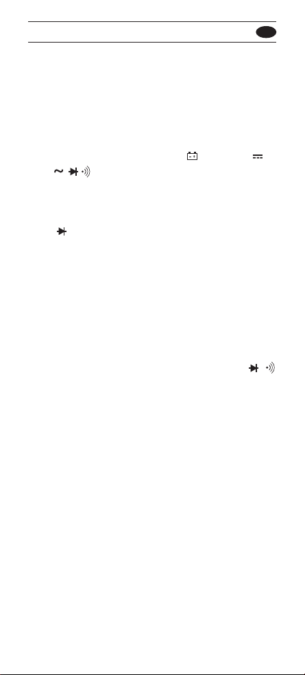
• Disconnect the test leads from the test points before
changing the position of the function rotary switch.
• Never voltage with the function rotary switch in
resistance, diode, continuity
• Do not expose Meter to extremes in temperature of high
humidity.
67 EN
2

INTRODUCTION
1-1 Unpacking and Inspection
Upon removing your new Digital Multimeter from its
packing, you should have the following items:
1. Digital Multimeter.
2. Test lead set (one black, one red).
3. Operators Manual.
4. Holster.
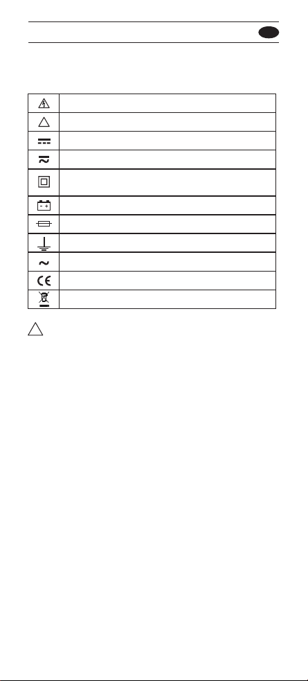
Symbols as marked on the Tester and
Instruction card
!Warning
When connecting the test leads to the DUT (Device Under
Test) connect the common test leads before connecting
the live test leads; When removing the test leads, remove
the live test leads before removing the common test leads.
67 EN
Risk of electric shock
See instruction card
DC measurement
Equipment protected by double or reinforced
insulation
Fuse
Battery
AC measurement
Conforms to EU directives
Do not discard this product or throw away.
Both direct and alternating current
!
Earth
3

1-2 Front Panel
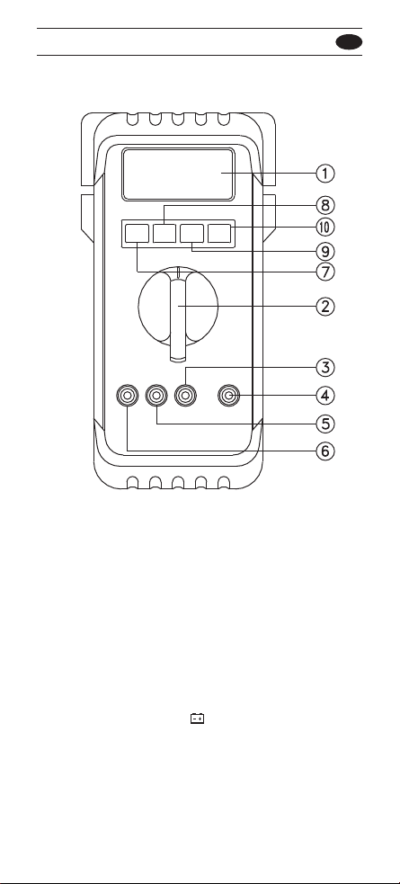
Refer to Figure 1 and the following numbered steps to
familiarize yourself with the meter's front panel controls
and connectors.
1. Digital Display — The digital display has a 3200
counts LCD readout with 65 segments analog bar
graph, auto polarity, decimal point, , HOLD, DC ,
AC , ,RANGE, and Unit annunciators.
2. Rotary Switch — Selects the desired function and
range.
3. COM Input Terminal — Ground input connector.
4. V Ω Input Terminal — Positive input connector for
Volts, Ohms and Diode measurements.
5. μA mA Input Terminal — Positive input connector for
current and measurements. (up to 300mA).
6. A Input Terminal — Positive input connector for current
measurements, up to 10A.
7. Function Switch (Blue) — Press the switch to
measure AC voltage or DC voltage in the Voltage mode
or to measure AC current or DC current in the current
mode, or to measure continuity or diode check in /
mode.
8. Reset Switch — The meter can be turned back on by
pushing "RESET" key switch.
9. Hold Switch — This switch is used to hold measured
values for all functions. When pressed the "HOLD"
annunciator is displayed. Conversions are made but the
display is not updated.
10. Range Switch (Manual Range) — The "Range"
switch is pressed to select manual ranging and to
change ranges. When the "Range" switch is pressed
once, the "RANGE" annunciator on the LCD
disappears. Press the "Range" switch to select the
appropriate range to be used. Press the "Range" switch
and hold for 2 seconds to return to Auto-ranging.
67 EN
4

SPECIFICATIONS
2-1 General Specifications
Display : The Liquid Crystal Display (LCD) has a
maximum reading of 3200, and 65 segments bar graph.
Polarity Indication : Automatic, positive implied, negative
indicated.
Overrange Indication : "OL" or "-OL", except 600V
Range.
Low Battery Indication : " " is displayed when the
battery voltage drops below operating voltage.
Sampling : 2 times/sec for digit. 12 times/sec for analog
bargraph.
Auto Power Off : Approximately 10 minutes unless the
measured value changes within this time.
Figure 1
67 EN
5

67 EN
Temperature Coefficient :
0.15 x (Specified accuracy) / °C, < 18°C or > 28°C.
Power Requirements :
IEC LR03, AM4 or AAA size 1.5V x 2.
Battery Life : Alkaline 900 hours.
Dimensions (HxWxD) :
66mm x 155mm x 34mm, without holster.
85mm x 165mm x 40mm, with holster.
Weight (including battery) :
250 gms, without holster / 370 gms, with holster.
Supplied Accessories : Test leads, battery (installed),
operator's manual and holster.
2-2 Environmental Conditions
For indoor use.
Maximum Altitude : 2000m.
Pollution Degree : 2
Operating Ambient : 0°C to 50°C, 0 to 80% R.H.
Storage Temperature : -20°C to 60°C, 0 to 80% R.H. with battery
removed from meter.
Installation Category : EN 61010-1, EN61010-2-033
CAT II.600V, CAT III.300V
EMC : EN61326-1
Shock Vibration : Sinusoidal Vibration per MIL-PRF-28800F
(5~55Hz, 3g Maximum)
Drop Protection : 4 feed drop to hardwood on concrete floor.
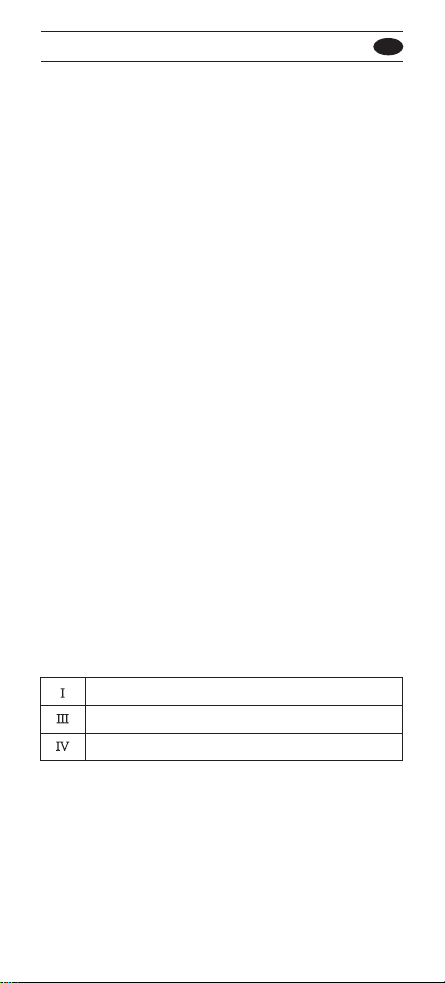
CAT Application field
IThe circuits directly connected to Low-voltage installation.
III The building installation.
IV The source of the Low-voltage installation.
2-3 Electrical Specifications
Accuracy is ± (% reading + number of digits) at 23°C ±
5°C less than 80% R.H.
Accuracy is specified for a period of one year after
calibration.
6
6

67 EN
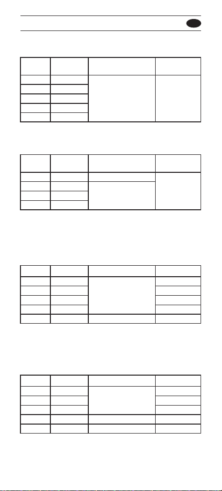
(1) DC Volts
Range Resolution Accuracy Over voltage
protection
300mV
100µV
3V 1mV 600Vd.c.
±(0.7%reading+2digits) or
30V 10mV 600Va.c.rms
300V 100mV
600V 1V
Input Impedance : 10MΩ.
(2) AC Volts
Range Resolution Accuracy Over voltage
protection
3V 1mV ±(1.7%reading+5digits)
30V 10mV 600Vd.c.
±(1.7%reading+5digits)
40Hz to 400Hz or
300V 100mV 600Va.c.rms
600V 1V
* Frequency Response : 40Hz ~ 300Hz for 3V Range.
AC Conversion Type : Average Sensing rms indication.
Input Impedance : 10MΩ //less than 100PF.
(3) DC Current
Range Resolution Accuracy Voltage Burden
300μA
0.1μA 200mV max
3mA 1μA 2V max
±(1.2%reading+2digitst)
30mA 10μA 200mV max
300mA 0.1mA 2V max
* 20A 10mA ±(2.5%reading+5digits) 2V max
* 20A Range : 30 seconds maximum above 10A input.
Overload Protection : 600mA/600V fast for μA/mA input.
12A/600V fast for A input.
(4) AC Current
Range Resolution Accuracy Voltage Burden
300μA
0.1μA 200mV max
3mA 1μA ±(1.7%reading+4digits) 2V max
30mA 10μA 200mV max
300mA 0.1mA ±(2.0%reading+4digits) 2V max
* 20A 10mA ±(2.9%reading+7digits) 2V max
7
7

67 EN
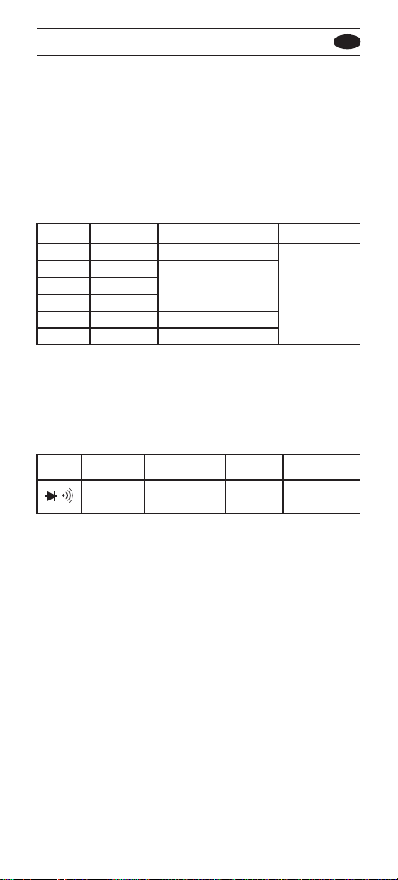
(5) Resistance
Range Resolution Accuracy Voltage Burden
300Ω 0.1Ω ±(1.2%reading+4digits)
3KΩ 1Ω 600Vd.c.
30KΩ 10Ω ±(0.9%reading+2digits) or
300KΩ 100Ω 600Va.c. rms
3MΩ 1KΩ ±(1.2%reading+3digits)
*30MΩ 10KΩ ±(2.5%reading+5digits)
* Open Circuit Voltage : 1.3V approx.
There is a little rolling less than ±50 digits when
measuring > 10.00 MΩ.
(6) Diode Check and Continuity
Range Resolution Accuracy Max. Test Max. Open
Current Circuit Voltage
1mV ±(1.5%reading
+ 5digits) 1.5mA 3.3V
*For 0.4V ~ 0.8V.
Overload Protection: 600V DC/AC rms max.
Continuity: Built-in sounder will operate when resistance is
less than 30Ω.
8
* Frequency Response : 40Hz ~ 500Hz.
* 20A Range : 30 seconds maximum above 10A input.
Overload Protection : 600mA/600V fast for μA/mA input.
12A/600V fast for A input.
AC Conversion Type : Average sensing rms indication.
(7) Auto Power Off
The meter will automatically shut itself off approximately
10 minutes after power on unless the value being
measured changes within this time. The meter can be
turned back on by pressing "Reset" key switch.
(8) Beep Guard
The beeper will sound if the test lead is connected to the μ
A/mA/(A) input terminal, but the rotary function selector is
not in the μA/mA/(A) positions.
8

67 EN
3-1 Preparation and Caution before Measurement
1. Before measurement, warm up for at least 30 seconds.
2. When the rotary function selector is changed during
measurement, be sure to do so only after removing the
test leads from the equipment.
3. If the equipment is used near noise generating
equipment, be aware that the display may become
unstable or indicate large errors.
4. Maximum rated voltage to earth for voltage and
current measurements terminals is 600V AC/DC CAT II.
3-2 Voltage Measurements
1. Connect the red test lead to the " V Ω " input terminal
and the black test lead to the "COM" terminal.
2. Set the rotary function switch to the ACV or DCV
position.
3. Connect the test leads to the device to be measured.
4. When the input is over-ranged the most significant digit
of LCD display flashes and the three last significant
digits are set to zero.
5. " Warning : Do not exceed 600Vd.c. or 600Va.c.
limits stated in the specification".
Warning
TO AVOID ELECTRIC SHOCK HAZARD, OR DAMAGE
TO THE METER, DO NOT ATTEMPT TO MEASURE
VOLTAGES THAT MIGHT EXCEED 600 VOLTS d.c. OR
600 VOLTS a.c.. DO NOT APPLY MORE THAN 600V
d.c. OR 600V a.c. RMS BETWEEN THE COMMON
INPUT TERMINAL AND EARTH GROUND.
3-3 Resistance Measurement
1. Connect the red test lead to the " V Ω " terminal and
the black test lead to the "COM" terminal.
2. Set the rotary function switch to the "Ω" position to
measure resistance.
!
!
!
9
Altri manuali per 67
1
Indice
Lingue:
Altri manuali APPA Multimetro
Manuali Multimetro popolari di altre marche

Gossen MetraWatt
Gossen MetraWatt METRAmax 6 Manuale utente

PeakTech
PeakTech 4000 Manuale per l'uso e la cura

YOKOGAWA
YOKOGAWA 90050B Manuale utente

Gossen MetraWatt
Gossen MetraWatt METRALINE DMM16 Manuale utente

Fluke
Fluke 8846A Manuale operativo e di manutenzione

Tempo Communications
Tempo Communications MM200 Manuale utente