Applied fire CFWS10 Manuale utente

Assembled in the USA
Model CFWS10
Owner’s Manual
• Activates When in Contact with Water
• Built in Freeze Alert
• For Use with the Comm Link and OmniShield App
• Internal Horn for Audible Feedback
• Backlit LED Icons for Signaling
• Long Life Internal Lithium Battery
Water Sensor

2
About Your New Water Sensor .......................................page 3
Contents of Your Kit ..................................................... page 4
General Warnings on Remote Notification .................... page 5
Acceptable Spacing for Sensors .................................... page 6
Setting Up Your New Water Sensor ............................... page 7
How to Install Your Water Sensor ...................................page 8
Where to Install Your Water Sensor ............................... page 9
Where NOT to Install Your Water Sensor ..................... page 10
Water Sensor Features and Functions .......................... page 11
FCC Compliance and IC Notice .................................... page 12
DISCLAIMER OF WARRANTIES ..................................... page 13
LIMITATION OF DAMAGES ........................................... page 14
Lifetime Fire/Flood Replacement Policy .......................page 15
Table of Contents
ATTENTION - This manual should be read, followed and
retained for future reference.
ALARMS AND SENSORS CANNOT GUARANTEE THAT YOU
WILL NEVER SUFFER INJURY OR DAMAGE FROM POTENTIAL
HAZARDS IN THE HOME

About Your New Water Sensor .......................................page 3
Contents of Your Kit ..................................................... page 4
General Warnings on Remote Notification .................... page 5
Acceptable Spacing for Sensors .................................... page 6
Setting Up Your New Water Sensor ............................... page 7
How to Install Your Water Sensor ...................................page 8
Where to Install Your Water Sensor ............................... page 9
Where NOT to Install Your Water Sensor ..................... page 10
Water Sensor Features and Functions .......................... page 11
FCC Compliance and IC Notice .................................... page 12
DISCLAIMER OF WARRANTIES ..................................... page 13
LIMITATION OF DAMAGES ........................................... page 14
Lifetime Fire/Flood Replacement Policy .......................page 15
About Your New Water Sensor
Illuminated icons for
Water and Freeze alerts
Test Button
Built-In Horn
Internal Lithium
Battery
Thank you for purchasing the Water Sensor made by Applied
Fire Technologies, LLC. When used in conjuction with the
company’s Comm Link and downloadable OmniShield App,
the Water Sensor plays a special role in protecting your home
from potentially costly water leaks. Please read and follow
the information in this booklet to ensure that your Water
Sensor performs at its best.
Gold-Plated
Sensor
3

4
Contents of Your Kit
Water
Sensor
Instruction
Manual
Key Features
• Alerts whenever water contacts the gold plated sensor
• Fully compatible with the Comm Link and OmniShield App
• Emits audible, visual and text/email warnings
• Powered by a long-life Lithium battery
• Supplied with multiple mounting options
• Acts as a low temperature freeze alert
2-Sided
Adhesive Feet
Rubber Feet
Vertical
Mounting
Screw
Please be sure the following are included in your kit:

General Warnings on Remote
Notification and Your Water Sensor
WARNING: While the Water Sensor and OmniShield
branded products are designed to produce cell phone and
Internet based warning messages, many factors can and
will affect their ability to do so. Things such as a poor
internet connection, poor cell phone reception, cell phones
turned off, cell phones out of battery, sensors placed out
of range, power outages, etc., will prevent messaging.
WARNING: Loss of electrical power or Internet connection
will prevent the unit from sending text/email messages.
WARNING: This product is intended for use in ordinary
indoor locations of family living units.
WARNING: Radio communication between units may
fail to take place if significant changes to the home have
occurred since installation and testing. Moving large
objects such as a refrigerator or metal cabinet could
impact performance.
NOTICE: Smoke, CO, Heat Alarms, Water Sensors, Bed
Shakers and Comm Links are not substitutes for an
adequate homeowner’s fire/property insurance policy.
WARNING: This device primarily requires remote
notification. Its horn is not loud enough to be relied
upon as the primary notifier of a water leak situation.
WARNING: Warning signals may not be heard. A deep
sleeper, hearing-impaired, young child or someone impaired
by drugs or alcohol may not awaken to an activation signal.
5

6
Acceptable Spacing for Sensors
Each sensor will also act as a
repeating station during alarm
conditions, so any signal received by
a device will be rebroadcast.
After installation, test all devices for Comm Link
reception. Simply press and release the test button
of a unit, then check your OmniShield App or text
messages.
Maximum
Spacing in
Open Area
200’ (70m)
The sensor-to-sensor radio
communicates using radio
frequencies between 905.2MHz and
913.2MHz. The range of this radio
has been tested to 200 ft (70m) in
open area distance testing. The
Comm Link’s WiFi communicates at
2.4GHz, which produces a shorter
indoor range.
Note: Please keep in mind that large
metal objects and other obstructions
to radio will likely reduce your radio
range.
General Note: Do not clean the exterior surfaces and gold/
red sensor with harsh detergents. This could damage the
unit. Clean with warm water and a damp cloth.

The Water Sensor should be tested monthly. This is
done either by pressing the “Test” button on the face or
by dampening the red/gold sensor on the back surface.
Thoroughly dry the sensor before replacing.
Setting Up Your New Water Sensor
Now that you’re familiar with your new Water Sensor, let’s get
them set up and installed!
The OmniShield App
At this point of your setup you should already
have the OmniShield App installed and open on
your phone. Make sure that your Comm Link is
in binding mode (see Comm Link manual).
Activate Your Water Sensor
To activate your Water Sensor, simultaneously
press the button on the front face while
touching the gold/red sensor on the back.
Install the Water Sensor
The Water Sensor will turn on and display a
flashing blue light. After the sensor has bound
with your Comm Link, the light will go out.
Using one of the mounting methods described
on Page 8, properly install the sensor in a
location that could potentially have a water
leak.
7

8
Notice: A very significant amount of water will be required
to accumulate before it can directly contact a wall-mounted
sensor. Be sure that no damage to the building/structure can
occur from this water build up.
How to Install Your Water Sensor
The Water Sensor is shipped with three different installation
options.
4X
PEEL
4 PLACES
Rubber Feet
The rubber feet are designed to prevent the
Water Sensor from sliding on the surface,
yet to allow for easy cleaning under the
unit. Just peel and stick the feet onto the
sensor.
2-Sided Adhesive Feet
The 2-sided adhesive feet are included to
create a more durable anti-sliding installation.
Use of these feet prevents all movement of the
device. Just peel the feet off the liner, stick
to the unit, then peel off the secondary liner.
Press the unit firmly to the floor/surface.
Mounting Screw
The mounting screw is included to allow
for wall mounting. In certain situations, a
user might prefer mounting the sensor on a
vertical surface, above the floor, or in a sump.

How to Install Your Water Sensor Where to Install Your Water Sensor
For the Water Sensor to contribute to your home’s protection,
it must be located near potential sources of water leaks.
Kitchens
Excellent locations for Water Sensors are
under sinks and dishwashers. Be sure that
the placement surface is clear and will allow
for a flow of water to reach the sensor.
Bathrooms
Placing a Water Sensor under the vanity sink
or near the toilet’s inlet valve adds protection
to the home.
Utility Closets and Basements
Locating a Water Sensor near the washing
machine or its inlet valves is a good
idea. Other locations can be under your
water heater or near the sump pump in a
basement.
Additional Recommended Locations
Some additional areas that could benefit from a Water Sensor
are: laundry rooms, ice makers, large fish tanks and indoor
decorative fountains.
9
10
Notice: The small clearance space beneath a water sensor and
the surface upon which it rests must be kept clean and clear.
Any build up of dirt, dust, animal hair, or other contaminants
can prevent water from reaching the unit’s sensor!
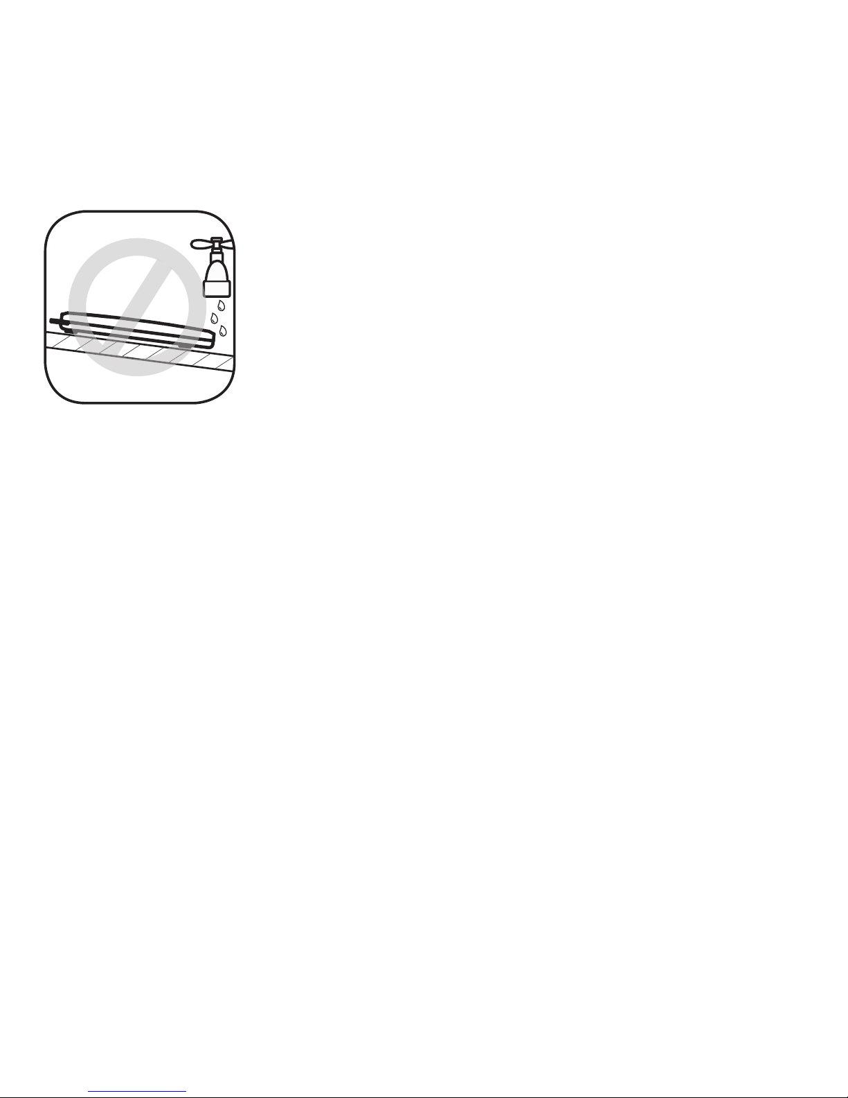
Where NOT to Install Your Water Sensor
In order for the Water Sensor to be effective, liquid water must
be able to contact the gold/red sensor on the underside.
Sloped Surfaces
The Water Sensor must be placed in such a way
as to ensure that water will move TOWARDS
the sensor. This is often the lowest spot on a
surface. The water must be free to flow, not
be absorbed into the ground.
If all of the Water Sensor’s feet are not resting on the surface
being protected, water may not be able to contact the gold/
red sensor. Ensure the unit is properly placed on the surface.
The gold/red sensor cannot directly contact metal or
conductive objects. This will cause a text message to be sent
stating repositioning is required.
WARNING: The radio built into the Water Sensor can be
affected by large metal objects like a water heater, washing
machine or cast iron sink. Be sure to fully test the Water
Sensor’s connection to the Comm Link at time of installation.
Additional Areas to NOT Install the Sensor
The Water Sensor must be positioned on materials that do
not absorb water. Water must be of sufficient quantity and
thickness to contact the underside of the unit.
Indice


