BridgeVMS BEU-4 Manuale utente

BEU-4 USER MANUAL
Version1.2.0
VP-4 User Manual
2
Regulatory Information
FCC Information
FCC compliance: This equipment has been tested and found to comply with the limits for a digital device,
pursuant to part 5 of the FCC Rules. These limits are designed to provide reasonable protection against harmful
interference when the equipment is operated in a commercial environment. This equipment generates, uses, and
can radiate radio frequency energy and, if not installed and used in accordance with the instruction manual, may
cause harmful interference to radio communications. Operation of this equipment in a residential area is likely to
cause harmful interference in which case the user will be required to correct the interference at his own expense.
FCC Conditions
This device complies with part 5 of the FCC Rules. Operation is subject to the following two conditions:
. This device may not cause harmful interference.
2. This device must accept any interference received, including interference that may cause undesired operation.
EU Conformity Statement
This product and - if applicable - the supplied accessories too are marked with "CE" and comply
therefore with the applicable harmonized European standards listed under the Low Voltage
Directive 2006/95/EC, the EMC Directive 2004/ 08/EC.
2002/96/EC (WEEE directive): Products marked with this symbol cannot be disposed of as
unsorted municipal waste in the European Union. For proper recycling, return this product to
your local supplier upon the purchase of equivalent new equipment, or dispose of it at
designated collection points. For more information see: www.recyclethis.info.
2006/66/EC (battery directive): This product contains a battery that cannot be disposed of as
unsorted municipal waste in the European Union. See the product documentation for specific
battery information. The battery is marked with this symbol, which may include lettering to
indicate cadmium (Cd), lead (Pb), or mercury (Hg). For proper recycling, return the battery to
your supplier or to a designated collection point. For more information see:
www.recyclethis.info.

VP-4 User Manual
3
Description on Laser Specification
The optical disc drive such as DVD Super Multi (Double Layer) Drive 22X that is used in this computer is
equipped with laser. The classification label with the following sentence is affixed to the surface of the drive.
CLASS LASER
PRODUCT TO IEC60825-
LASER KLASSE
The drive with the above label is certified by the manufacturer that the drive complies with the requirement for
laser product on the date of manufacturing pursuant to article 2 of Code of Federal Regulations by the United
States of America, Department of Health & Human Services, Food and Drug Administration.
In other countries, the drive is certified to comply with the requirement pursuant to IEC 60825- and EN 60825-
on class laser product.
This computer is equipped with the optical disc drive in the following list according to the model.
VP-4 User Manual
4
Safety Warnings and Cautions
Please pay attention to the follo ing arnings and cautions:
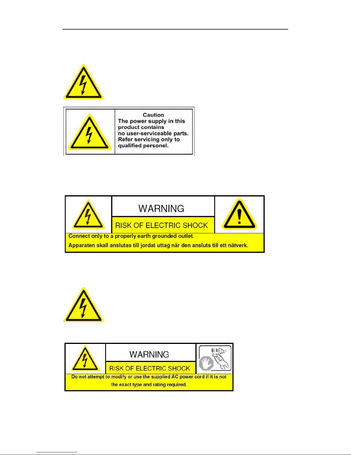
Hazardous Voltage may be present: Special measures and precautions must be taken
when using this device. Some potentials (voltages) on the device may present a hazard to
the user. This device should only be used by employees from our company with knowledge
and training in working with these types of devices that contain live circuits.
Po er Supply Hazardous Voltage: AC mains voltages are present within the power supply assembly. This device
must be connected to a UL approved, completely enclosed power supply, of the proper rated voltage and current.
No user serviceable parts inside the po er supply.
System Grounding (Earthing): To avoid shock, ensure that all AC wiring is not exposed and that the earth
grounding is maintained. Ensure that any equipment to which this device will be attached is also connected to
properly wired grounded receptacles and are approved medical devices.
Po er Connect and Disconnect: The AC power supply cord is the main disconnect device
to mains (AC power).The socket outlet shall be installed near the equipment and shall be
readily accessible.
Installation and Maintenance: Do not connect/disconnect any cables to or perform
installation/maintenance on this device during an electrical storm.
Po er Cord Requirements: The connector that plugs into the wall outlet must be a grounding-type male plug
designed for use in your region. It must have certification marks showing certification by an agency in your region.

VP-4 User Manual
5
The connector that plugs into the AC receptacle on the power supply must be an IEC 320, sheet C 3, female
connector. See the following website for more information http://kropla.com/electric2.htm.
Lithium Battery: This device contains a Lithium Battery. There is a risk of explosion if
the battery is replaced by an incorrect type. Dispose of used batteries according to the
vendor’s instructions and in accordance with local environmental regulations.
Perchlorate Material: Special handling may apply. See
www.dtsc.ca.gov/hazardouswaste/perchlorate. This notice is required by California Code
of Regulations, Title 22, Division 4.5, Chapter 33: Best Management Practices for Perchlorate Materials. This
device includes a battery which contains perchlorate material.
Chapter 1 Introduction
1.1 Description
Developed on the basis of the latest encoding technology, the BEU-4 allows the analog signal to be digitized and
then stored in hard disk or transmitted via network.
Adopting the latest embedded processor, the BEU-4 provides more powerful capabilities in audio/video encoding;
standard U chassis design maintains easy installation; multiple network transmission protocols supported; and
code downloaded in FLASH ensures high stability and reliability of system performance.
1.2 Features
Encoding
Support H.264 encoding standard at PS and RTP customized encapsulation formats, of which RTP stream is used
for transmission via network and PS stream for recording;
Support encoding at 4CIF, 2CIF, CIF and QCIF resolutions;
Dual stream encoding;
Either compound streams encoding or video stream encoding selectable; audio and video synchronization during
compound streams encoding.
Recording
Multiple Recording Periods Configurable
Up to 8 recording periods can be configured for each day, with different recording type selectable for each
recording period.
Cycle Recording
Either cycle recording or non-cycle recording mode is configurable. In cycle recording mode, the earliest recoding
will be overwritten when the HDD is full; and in non-cycle recording mode, the system will stop recording and
give alert when HDD is full.
Scheduled & Event Recording
Each channel can be set with the scheduled recording and event recording separately, with separate resolution, bit
rate, frame rate and stream type configurable.

VP-4 User Manual
6
Multiple Record Triggering Modes
Scheduled recording;
Motion detection recording;
Alarm recording;
Motion detection/alarm recording;
Motion detection & alarm recording;
Manual recording.
Pre-recoding and Post-recording
Support pre-recoding and post-recoding, with the recording time configurable: 0-30sec for pre-recording and
5-600sec for post-recording;
Record Files Lock & Unlock
User may lock/unlock the record files, and the locked record files will not be overwritten in cycle-recording mode.
HDD Group Management
HDD Property Settings
The HDD can be set to read/write, read-only or redundancy properties;
When the HDD is set to read-only, it allows search and playback of record files only, and no data can be written
into the disk, including record and log;
When the HDD is set to redundancy, it must be used with the read/write disk for real-time backup of important
record data.
Net ork
One 0M/ 00Mbps self-adaptive UTP Ethernet interface;
IPv6 is supported.
TCP/IP protocol, PPPoE, DHCP, DNS, DDNS, NTP, SADP, SMTP, SNMP, NFS, and iSCSI are supported.
TCP and UDP for unicast.
Automatically get IP address by DHCP protocol;
Two-way audio and single-directional broadcasting;
Transmission via RS-232 and RS-485 transparent channels;
Access to Internet by PPPoE method, and support Peanut Hull, Dyndns, NO-IP, etc.;
Set time by NTP;
Remote Web browser access by HTTP protocol;
Connectable with network HDD in NAS, IPSAN mode;
Send E-mail by SMTP protocol, and support attachment of captured JPEG image and SSL encryption;
Remote JPEG image capturing with user-defined image resolution and quality.
PTZ Control
Support Multiple PTZ Protocols
Different channels can be configured with protocol type, RS-485 address, baud rate, data bit, stop bit, even & odd
parity, stream control method, etc.; and remote configuration of presets, patrols and patterns.
Digital Zoom ( ith Speed Dome)
When connected with speed dome, digital zooming can be realized by clicking on the image through client
software.
PTZ linkage
Relay input alarm can be responded with PTZ linkage actions, e.g., callup of predefined presets, patrols or
patterns.
Alarm

VP-4 User Manual
7
Relay Alarm Input
Either NO mode or NC mode can be set;
Four different alarm arming periods are configurable;
Capabilities of triggering corresponding alarm handling methods, relay alarm output, buzzer alarm, upload to
control center, PTZ linkage, presets/patrols/patterns callup, etc.
Relay Alarm Output
Relay alarm output can be connected with alarm devices for alarm handling within arming period.
Exceptions
Exception Alarm Handling
Exception alarms include network disconnect alarm, IP address conflict alarm, illegal access alarm, etc.; multiple
alarm handling methods are supported, relay alarm output, buzzer alarm, upload to center, etc.
Exception Reboot
Software watchdog capability: for inspecting important tasks and system resources of device; in case of exceptions
detected, the device will be automatically rebooted.
Firmware watchdog: for inspecting the firmware of device; in case of exceptions in system task scheduling, the
device will be automatically rebooted.
User Administration
A maximum of 32 users can be created by the system, including administrator and 3 users. The user name of the
administrator is admin, which cannot be modified, and the password is allowable to be modified by the
administrator only; no deletion of the administrator is allowed, and the administrator is authorized to set the
operation permissions for normal users.
Logs
The system logs can be classified into the operation logs, alarm logs, exception logs and information logs. User
may search and view all recorded system logs by date or type, as well as export the logs to the text format over
network.
VP-4 User Manual
8
Chapter 2 Structure
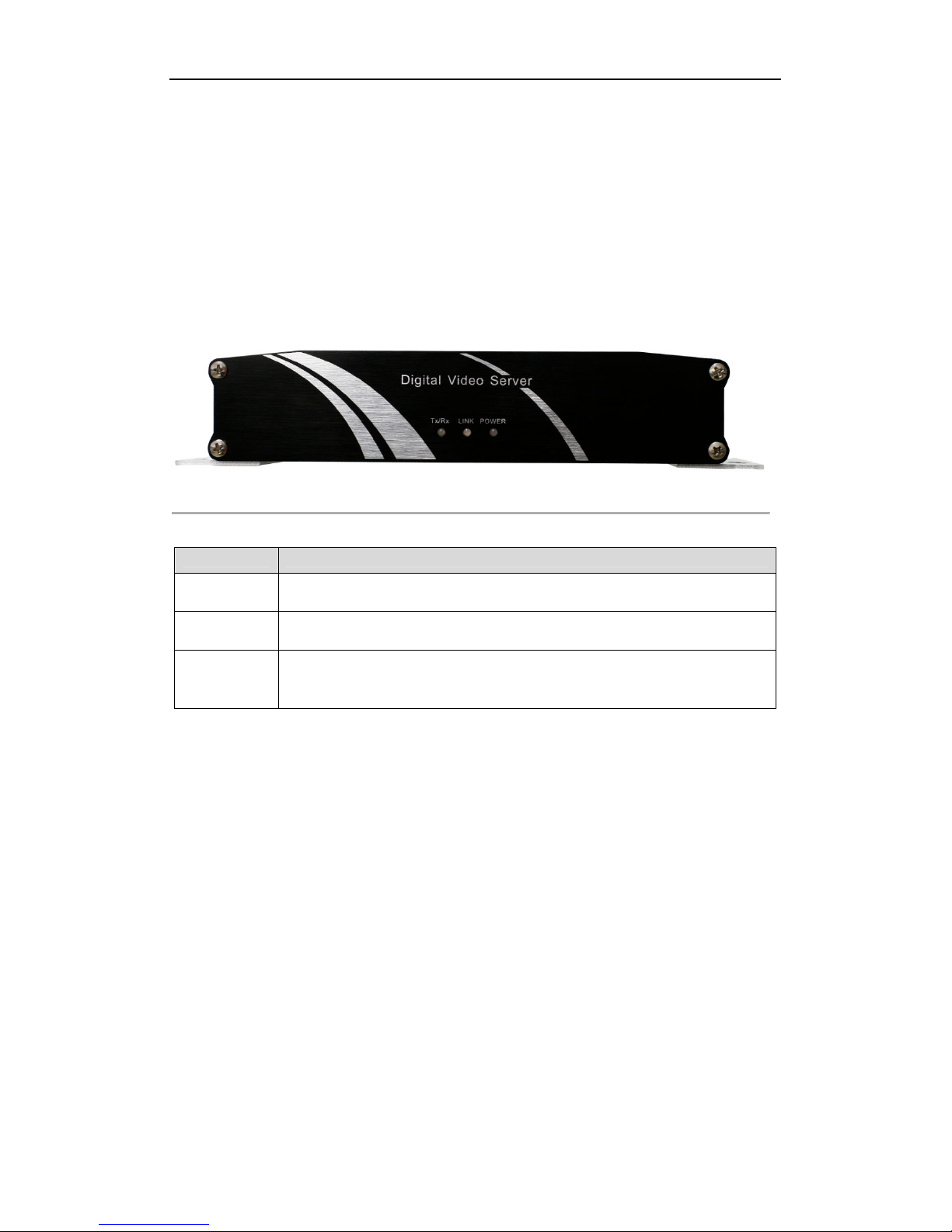
2.1 Front Panel
VP-4:
Figure 2. Front Panel of BEU-4
Table 2. Front Panel of BEU-4
LED Indicator Function
POWER Power LED indicator: . Lights in red when the device is working; 2. Does not light when
the device is powered off.
LINK LINK LED indicator: . Normally lights in green when the network connection is
functioning properly; 2. Does not light when the network connection is abnormal.
Tx/Rx Tx/Rx LED indicator: . Does not light when the network is not connected; 2. Blinks in
green when the data is transmitting / receiving; 3. Blinks at higher frequency when the data
for transmitting / receiving is larger.
2.2 Rear Panel

VP-4 User Manual
9
BEU-4HCI / HFI:
Figure 2.2 Rear Panel of BEU-4
Table 2.2 Rear Panel of BEU-4
Interface Connections
GND Grounding
2 DC 2V 2V DC power supply
3 RS-485 RS-485 serial interface for connection to pan/tilt unit, speed dome, etc.
4 ALARM OUT Relay alarm output.
5 ALARM IN Relay alarm input.
6 RESET Restore the factory default settings by holding the RESET button for 5
seconds after power is turned on.
7 LAN 0M/ 00Mbps self-adaptive UTP Ethernet interface.
8 RS-232 Serial interface for configuration of device’s parameters or used as
transparent channel.
9 VIDEO IN BNC connectors for video input.
0 AUDIO IN BNC connectors for audio input.
LINE IN 3.5mm two-way audio input interface for connection to active pick-up,
microphone, etc.
2 AUDIO OUT 3.5mm audio output interface for connection to audio output device, e.g.,
loudspeaker, etc.
Rear Panel Pic
VP-4 User Manual
10
2.3 Alarm Connections
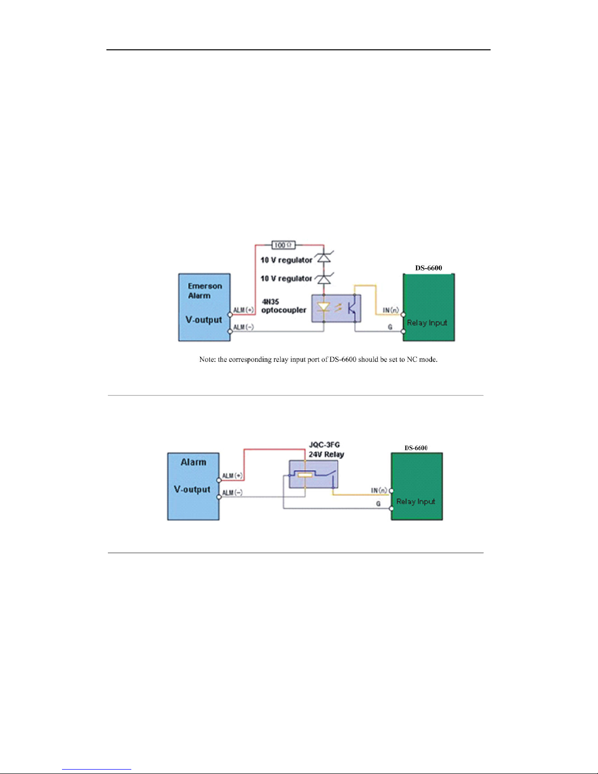
2.3.1 Alarm Input Connections
BEU-4 supports the
open/close
relay input as the alarm input mode. For the alarm input signal not in open/close
relay signal mode, please follow the connections shown as below:
Alarm input connections for Emerson Alarm:
Figure 2.3 Alarm Input Connections for Emerson Alarm
Alarm input connections for Normal Alarm:
Figure 2.4 Alarm Input Connections for Normal Alarm
2.3.2 Alarm Output Connections
BEU-4 supports the open/close relay input as the alarm output mode. The alarm input can be selected to NO or NC.
Different alarm output connection methods are applied to the AC or DC load. Please refer to the following
diagram:
Alarm output connections diagram:
Indice


