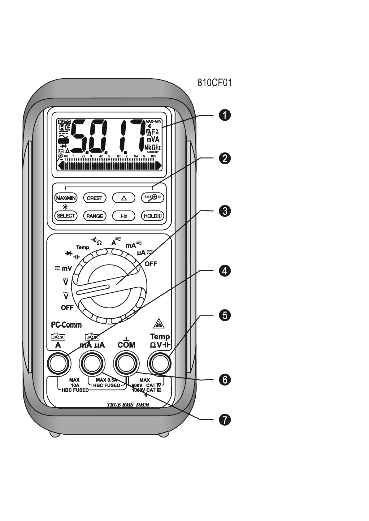
Brymen BM811s Manuale utente

USER'S
MANUAL
BM811s
BM812s
BM815s
BM817s

1
This manual is applicable to all meter protection versions or otherwise specified
1) SAFETY
Terms in this manual
WARNING identifies conditions and actions that could result in serious injury or even
death to the user.
CAUTION identifies conditions and actions that could cause damage or malfunction
in the instrument.
This manual contains information and warnings that must be followed for operating the
instrument safely and maintaining the instrument in a safe operating condition. If the
instrument is used in a manner not specified by the manufacturer, the protection
provided by the instrument may be impaired. The meter is intended only for indoor use.
The meter protection rating, against the users, is double insulation per
IEC/UL/EN61010-1 Ed. 3.0, IEC/EN61010-2-030 Ed. 1.0, IEC/EN61010-2-033 Ed. 1.0,
IEC/UL/EN61010-031 Ed. 1.1 and CAN/CSA-C22.2 No. 61010-1-12 Ed. 3.0 to
Category III 1000 Volts AC & DC and Category IV 600 Volts AC & DC.
Terminals (to COM) measurement category:
V / A / mAA : Category III 1000 Volts AC & DC, and Category IV 600 Volts AC & DC.
Per IEC61010-1 Measurement Category
Measurement Category IV (CAT IV) is for measurements performed at the source of
the low-voltage installation. Examples are electricity meters and measurements on
primary overcurrent protection devices and ripple control units.
Measurement Category III (CAT III) is for measurements performed in the building
installation. Examples are measurements on distribution boards, circuit- breakers,
wiring, including cables, bus-bars, junction boxes, switches, socket-outlets in the fixed
installation, and equipment for industrial use and some other equipment, for example,
stationary motors with permanent connection to the fixed installation.
Measurement Category II (CAT II) is for measurements performed on circuits directly
connected to the low voltage installation. Examples are measurements on household
appliances, portable tools and similar equipment.

2
WARNING
To reduce the risk of fire or electric shock, do not expose this product to rain or
moisture. To avoid electrical shock hazard, observe the proper safety precautions
when working with voltages above 60 VDC or 30 VAC rms. These voltage levels pose
a potential shock hazard to the user. Do not touch test lead tips or the circuit being
tested while power is applied to the circuit being measured. Keep your fingers behind
the finger guards of the test leads during measurement. Inspect test leads, connectors,
and probes for damaged insulation or exposed metal before using the instrument. If
any defects are found, replace them immediately. Do not measure any current that
exceeds the current rating of the protection fuse. Do not attempt a current
measurement to any circuit where the open circuit voltage is above the protection fuse
voltage rating. Suspected open circuit voltage should be checked with voltage
functions. Never attempt a voltage measurement with the test lead inserted into the
A/mA or A input jack. Only replace the blown fuse with the proper rating as specified
in this manual. Only use the test lead provided with the equipment or UL Listed Probe
Assembly rated CAT III 1000V or better.
CAUTION
Disconnect the test leads from the test points before changing functions. Always set
the instrument to the highest range and work downward for an unknown value when
using manual ranging mode.
INTERNATIONAL ELECTRICAL SYMBOLS
!
Caution ! Refer to the explanation in this Manual
Caution ! Risk of electric shock
Earth (Ground)
Double Insulation or Reinforced insulation
Fuse
AC--Alternating Current
DC--Direct Current
2) CENELEC DIRECTIVES
The instruments conform to CENELEC Low-voltage directive 2006/95/EC and
Electromagnetic compatibility directive 2004/108/EC

3
3) PRODUCT DESCRIPTION
Panel Illustration
1) 3-4/5 digits 5000 counts
LCD display
2) Push-buttons for special
functions & features
3) Selector to turn the
Power On or Off and Select
a function
4) Input Jack for 10A (20A
for 30sec) current function
5) Input Jack for all
functions EXCEPT current
(A, mA, A) functions
6) Common (Ground
reference) Input Jack for all
functions
7) Input Jack for milli-amp
and micro-amp current
functions

4
Analog bar-graph
The analog bar graph provides a visual indication of measurement like a traditional
analog meter needle. It is excellent in detecting faulty contacts, identifying
potentiometer clicks, and indicating signal spikes during adjustments.
Average sensing RMS calibrated
RMS (Root-Mean-Square) is the term used to describe the effective or equivalent DC
value of an AC signal. Most digital multimeters use average sensing RMS calibrated
technique to measure RMS values of AC signals. This technique is to obtain the
average value by rectifying and filtering the AC signal. The average value is then
scaled upward (calibrated) to read the RMS value of a sine wave. In measuring pure
sinusoidal waveform, this technique is fast, accurate and cost effective. In measuring
non-sinusoidal waveforms, however, significant errors can be introduced because of
different scaling factors relating average to RMS values.
True RMS
True RMS is a term which identifies a DMM that responds accurately to the effective
RMS value regardless of the waveforms such as: square, sawtooth, triangle, pulse
trains, spikes, as well as distorted waveforms with the presence of harmonics.
Harmonics may cause :
1)Overheated transformers, generators and motors to burn out faster than normal
2)Circuit breakers to trip prematurely
3)Fuses to blow
4)Neutrals to overheat due to the triplen harmonics present on the neutral
5)Bus bars and electrical panels to vibrate
Crest Factor
Crest Factor is the ratio of the Crest (instantaneous peak) value to the True RMS
value, and is commonly used to define the dynamic range of a True RMS DMM. A pure
sinusoidal waveform has a Crest Factor of 1.4. A badly distorted sinusoidal waveform
normally has a much higher Crest Factor.
NMRR (Normal Mode Rejection Ratio)
NMRR is the DMM's ability to reject unwanted AC noise effect that can cause
inaccurate DC measurements. NMRR is typically specified in terms of dB (decibel).
This series has a NMRR specification of >60dB at 50 and 60Hz, which means a good
ability to reject the effect of AC noise in DC measurements.
CMRR (Common Mode Rejection Ratio)
Common mode voltage is voltage present on both the COM and VOLTAGE input

5
terminals of a DMM, with respect to ground. CMRR is the DMM's ability to reject
common mode voltage effect that can cause digit rolling or offset in voltage
measurements. This series has a CMRR specifications of >60dB at DC to 60Hz in ACV
function; and >120dB at DC, 50 and 60Hz in DCV function. If neither NMRR nor CMRR
specification is specified, a DMM's performance will be uncertain.
4) OPERATION
CAUTION
Before and after hazardous voltage measurements, test the voltage function on a
known source such as line voltage to determine proper meter functioning.
DC Voltage, AC Voltage, & Hz Frequency functions
mV function defaults at DC. Press SELECT button momentarily to select AC. Press the
Hz push-button momentarily to activate or to exit Hz.
Note: Input sensitivity varies automatically with function range selected before activating
the Hz function. mV function has the highest (300mV) and the 1000V range has the
lowest (300V). It is recommended to first measure the signal voltage (or current) level
then activate the Hz function in that voltage (or current) range to automatically set the
most appropriate trigger level. You can also press the RANGE button momentarily to
select another trigger level manually. If the Hz reading becomes unstable, select lower
sensitivity to avoid electrical noise. If the reading shows zero, select higher sensitivity.

6
Capacitance, Diode test function
Default at . Press SELECT button momentarily to select Diode test function.
CAUTION
Discharge capacitors before making any measurement. Large value capacitors should
be discharged through an appropriate resistance load.
Normal forward voltage drop (forward biased) for a good silicon diode is between
0.400V to 0.900V. A reading higher than that indicates a leaky diode (defective). A
zero reading indicates a shorted diode (defective). An OL indicates an open diode
(defective). Reverse the test leads connections (reverse biased) across the diode. The
digital display shows OL if the diode is good. Any other readings indicate the diode is
resistive or shorted (defective).
Temperature function (Models 815s& 817sonly)
Press SELECT button momentarily to toggle between C and F readings, and the
new setting will be saved automatically in the non-volatile memory as power up default.

7
Note: Be sure to insert the banana plug K-type temperature bead probe Bkp60 with
correct polarities. You can also use a plug adapter Bkb32 (Optional purchase)
with banana pins to K-type socket to adapt other standard K type mini plug
temperature probes.

8
Resistance, Continuity functions
Default at . Press SELECT button momentarily to select Continuity function that is
convenient for checking wiring connections and operation of switches. A continuous
beep tone indicates a complete wire.
CAUTION
Using resistance and continuity function in a live circuit will produce false results and
may damage the instrument. In many cases the suspected component must be
disconnected from the circuit to obtain an accurate reading
Auto leads resistance calibration
When entering the 50range manually by RANGE button for high precision low
resistance measurement, this feature will prompt you to short the inputs for calibration.
The display shows “Shrt”. Simply short the leads for about 3 seconds until the display
shows zero, then the resistance in the leads and in the internal protection circuitry of
the meter is compensated automatically. The compensation value can be as much as
5. If you need a compensation value that is higher than that, Relative mode is
recommended.
The shortcut is to short the test leads in auto-ranging resistance mode until the meter

9
enters the lowest 50
range automatically, press the RANGE button momentarily to
get the “Shrt” prompt, then wait about 3 more seconds until the display shows zero.
Note: The calibration stays until you change ranges, functions, or go back to auto-
ranging mode.
A, mA, and A Current functions
Default at DC. Press SELECT button momentarily to select AC.
*Note: When measuring a 3-phase system, special attention should be taken to the
phase-to-phase voltage which is significantly higher than the phase-to-earth voltage.
To avoid exceeding the voltage rating of the protection fuse(s) accidentally, always
consider the phase-to-phase voltage as the working voltage for the protection fuse(s).
PC-COMM computer interface capabilities
The instrument equips with an optical isolated interface port at the meter back for data
communication. Optional purchase PC interface kit BRUA-85Xa (BC-85Xa RS232C
optical adapter cable + Bs8151X software CD + BUA-2303 USB-to-Serial adaptor) is
required to connect the meter to the PC computer. The Bs8151X Data Recording
System software equips with a digital meter, an analog meter, a comparator meter, and
a Data Graphical recorder. Refer to the README file in the interface kit for further
details.
Questo manuale è adatto per i seguenti modelli
3
Indice
Altri manuali Brymen Strumento di misura


