Page
CDK Electronics Ltd, 17/19, Buxton Road, Congleton, Cheshire. CW12 2DW.
Tel 01260 296300. Fax 01260 296301.
www.cdk.co.uk
3
DC68K Pack Controller - Issue 1.1a - Sept 2001
INTRODUCTION .......................................................................................................................................... 4
NORMAL RUNNING.................................................................................................................................... 5
High Pressure Override. .............................................................................................................................. 5
LP Pressure Override................................................................................................................................... 5
SYSTEM BACKUP & FAILURE MODES. ................................................................................................ 6
INSTALLATION ........................................................................................................................................... 7
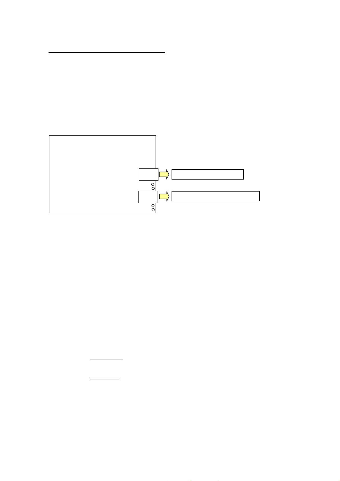
Wiring........................................................................................................................................................... 7
Power supply ................................................................................................................................................ 7
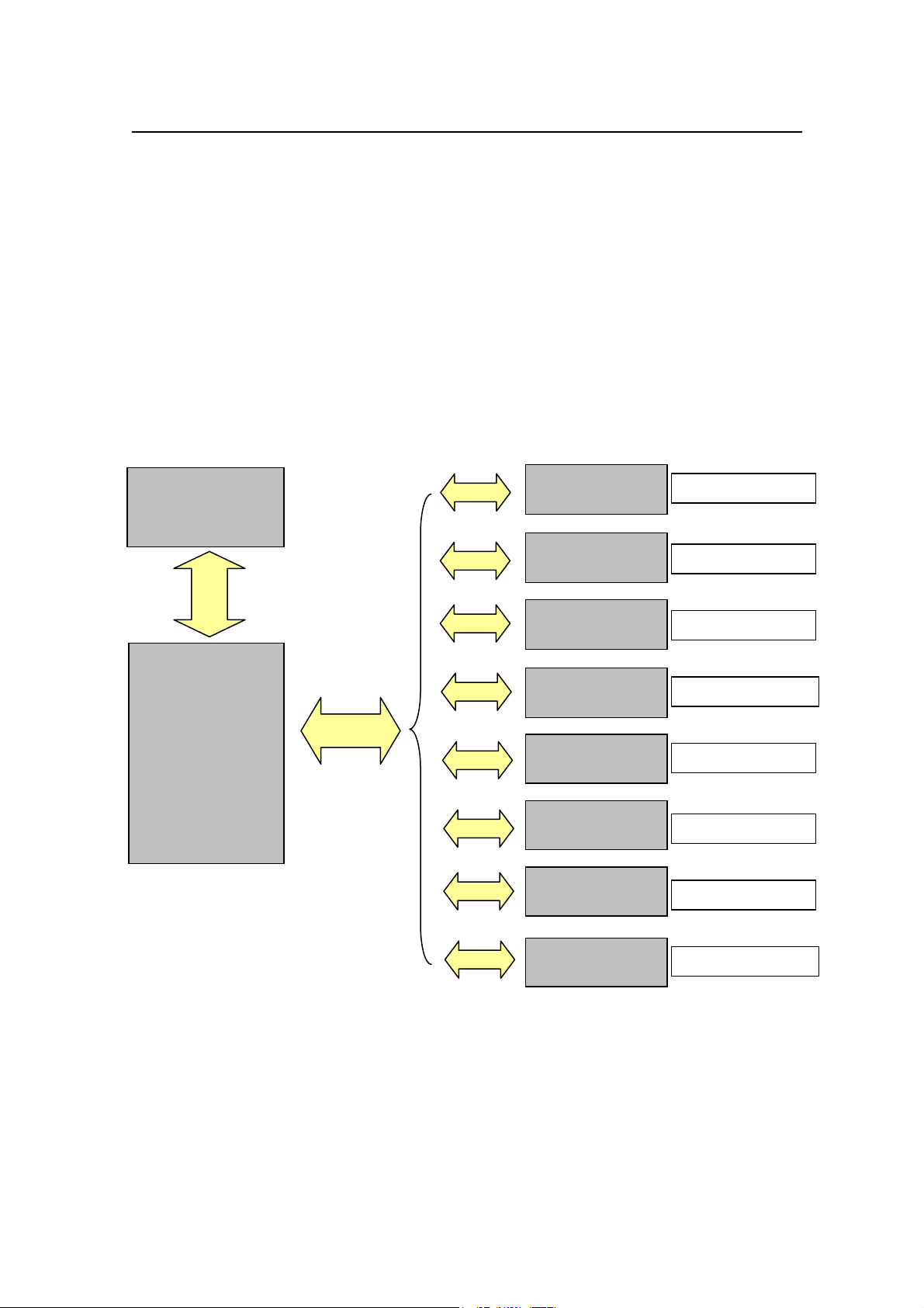
Communications Network Connections........................................................................................................ 8
Communications Address. ............................................................................................................................ 9
CONFIGURING THE SYSTEM ................................................................................................................ 10
Programming the DC68K........................................................................................................................... 10
System Configuration. ................................................................................................................................ 10
Adjusting the Control Settings.................................................................................................................... 12
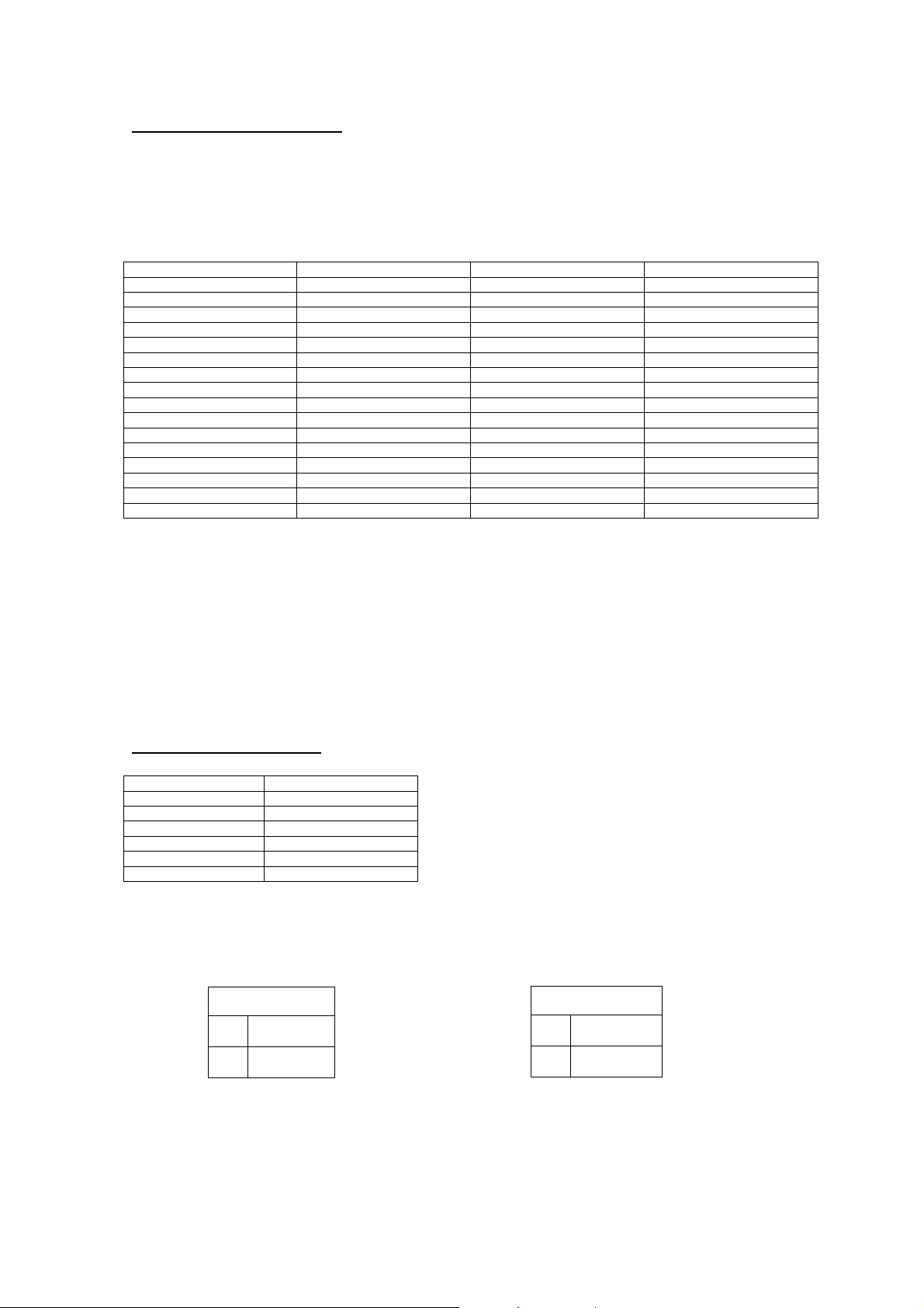
CONTROL SETTINGS............................................................................................................................... 13
DEFAULT CONTROL SETTINGS........................................................................................................... 16
FINE TUNING THE SYSTEM................................................................................................................... 17
SYSTEM STATUS ....................................................................................................................................... 18
SPECIFICATIONS. ..................................................................................................................................... 19
Technical. ................................................................................................................................................... 19
LIST OF FIGURES...................................................................................................................................... 20
USER MANUAL ISSUE UPDATES. ......................................................................................................... 21