Chromalox MAXPAC PK480 Manuale utente

PK480
P/N 0037-75428
User's Manual
www.chromalox.com
800-443-2640
© 2002 Chromalox, Inc.

- 1 -
© 2002 Chromalox®, Inc.1-888-996-9258
Thank you for choosing he Chromalox® MaxPac™ - a comple e power con rol solu ion wi h indus ry-bes
price and performance.
For more han 80 years, cus omers have relied on Chromalox for he u mos in quali y and innova ive solu ions
for indus rial hea ing applica ions. Chromalox manufac ures he world’s larges and broades line of elec ric hea
and con rol produc s.
The MaxPac Series SCR Con rollers provide he bes con rol for applica ions where consis en hea er/process
empera ure is cri ical or where fine resolu ion of power is required.
Common MaxPac features include:
• 120 - 575 Vac @ 100 - 1200 Amps
• Isola ed Con rol Circui
• Flexible I/O Power Wiring
• Easy Cus omer In erface
• Remo e Shu down
• Compac Size and Cons ruc ion
• Touch-Safe Design (op ion on 100 - 650 Amp models)
• dv/d Transien Vol age Pro ec ion
• MOV Pro ec ion
• Buil -In Power Dis ribu ion
Features for the MaxPac I, II, and III include:
• Zero Crossover Firing
• Isola ed Con rol Circui
On/Off Con rol Inpu s:
120 hru 240 Vac
5 - 32 Vdc
Dry Con ac Closure
Propor ional (DOT Firing) Inpu s:
4 - 20 mA, 0-5 Vdc, 1 - 5 Vdc, 0 - 10 Vdc
Remo e Manual Adjus
Remo e Au o/Manual Swi ch
• Elec ronically Pro ec ed wi h Tempera ure Warning and Shu down Sys em
• Single- or Three-Cycle Resolu ion (Jumper Selec able)
• Shor ed SCR De ec ion (Op ional)
Features for the MaxPac IP include:
• Phase Angle Firing
• Isola ed Con rol Circui Inpu s
0 - 5 mA, 0 - 20 mA
0 - 50 mA, 1 - 5 mA
4 - 20 mA, 10 - 50 mA
0 - 5 Vdc, 0 - 10 Vdc
• Op ional Curren Limi
• Sof S ar
• Line Vol age Compensa ion
• Zero & Gain Adjus men s
• Buil -In Manual Adjus men
• Curren Limi Adjus men (Op ional)
If you have applica ion ques ions, refer o he Engineering Resource sec ion of our websi e a
www.chromaloxhea ing.com o find he answer you’re looking for, or call one of our applica ion
engineers a 1-888-996-9258 for personal assis ance.

- 2 - © 2002 Chromalox®, Inc. 1-888-996-9258
○○○○○○○○○○○○○○○○○○○
Table of Contents
Section Topic Page
1 ................................................ Impor an Safeguards ...................................................................................... 3
2 ................................................ Descrip ion ...................................................................................................... 4
3 ................................................ Before You Ins all ............................................................................................ 5
4 ................................................ Ins alla ion ....................................................................................................... 6
4.1 ................................ Moun ing ........................................................................................................ 8
4.2 ................................ Wiring ........................................................................................................... 11
4.2.1 ................ Touch-Safe Design ....................................................................................... 11
4.2.2 ................ Cover Removal and Ins alla ion ................................................................... 12
4.2.3 ................ Power/Load Wiring ....................................................................................... 12
4.2.4 ................ Ins rumen Power ......................................................................................... 16
4.2.5 ................ Grounding ..................................................................................................... 16
4.2.6 ................ Command Signal Wiring............................................................................... 17
4.2.7 ................ Calibra ion .................................................................................................... 23
5 ................................................ Specifica ions ............................................................................................... 24
6 ................................................ Main enance ................................................................................................. 25
7 ................................................ Troubleshoo ing ............................................................................................ 26
8 ................................................ Par s and Accessories .................................................................................. 27
9 ................................................ Warran y and Re urn Informa ion ................................................................. 28
10 .............................................. EC Declara ion of Conformi y ....................................................................... 37

- 3 -
© 2002 Chromalox®, Inc.1-888-996-9258
1
Please read all ins ruc ions before ins alling and opera ing your MaxPac™.
To avoid elec rical shock or injury, always remove power before servicing a circui .
Personnel working wi h or near high vol ages should be familiar wi h modern me hods of resusci a ion. Con ac
an area supervisor or safe y personnel for more informa ion.
Throughou he MaxPac User Manual, he safe y aler and he in erna ional elec ric shock/elec rocu ion
symbols will aler you o po en ial hazards. Safe y precau ions should always be followed o reduce he risk of
personal injury o persons from fire and elec rical shock hazards.
Safe y Aler Symbol
In erna ional Shock/Elec rocu ion Symbol
Each safe y message is preceded by a safe y aler symbol and one of hree words: DANGER, WARN-
ING, or CAUTION.
These mean:
○○○○○○○○○○○○○○○○○○○○○○○○
Important Safeguards
You WILL be killed or seriously hur if you do no follow ins ruc ions.
You CAN be killed or seriously hur if you do no follow ins ruc ions.
You CAN be hur if you do no follow ins ruc ions.
DAN ER
WARNIN
CAUTION
Damage Preven ion Messages:
You will see o her IMPORTANT messages ha are proceeded by he word ha are in ended o
help preven damage o he MaxPac™ or o her equipmen . No e ha Damage Preven ion Messages are NOT
accompanied by he Safe y Aler Symbol.
CAUTION

- 4 - © 2002 Chromalox®, Inc. 1-888-996-9258
2
† This can be se o hree cycles ‘On’ / hree cycles ‘Off’ (see sec ion on ins alla ion op ions).
○○○○○○○○○○○○
Description
MaxPac I, II, and III
The Chromalox MaxPac I, II, and III con rollers are highly versa ile SCR Power Paks wi h op ional plug-in
propor ional firing and shor ed SCR de ec ion boards. Firing modes include On/Off and DOT propor ional zero
vol age swi ching. Chromalox exclusive DOT (Demand Orien ed Transfer) firing echnique swi ches he fewes
number of cycles o provide he mos precise zero crossover con rol. A 50% ou pu , he uni ’s ou pu al er-
na es be ween one cycle “On” and one cycle “Off.” A 51%, he ou pu con inues wi h one cycle “On,” one
cycle “Off,” and gradually in egra es one ex ra “On” cycle for he addi ional 1%. This DOT fired echnique also
minimizes empera ure overshoo , empera ure fluc ua ions and helps ex end he load’s elemen life due o
reduced hermal shock.
The power SCR assemblies consis of one, wo, or hree pairs of SCRs connec ed back o back (wi h an
op ional semiconduc or fuse), RC Snubber, and MOV pro ec ion. The firing circui is based on a common On/Off
con rol board wi h plug and play Shor ed SCR and DOT fired plug-in boards. Diagnos ic indica ors are included.
Plug-in erminal blocks for easy cus omer in erface are also provided.
MaxPac IP
The Chromalox MaxPac IP u ilizes Single Phase, Phase Angle firing o modula e power o an induc ive or
resis ive load. Phase Angle con rol has he advan age of propor ioning every cycle hereby providing very fine
resolu ion of power. Fas responding loads in which he resis ance changes as a func ion of empera ure
require Phase Angle con rol. The MaxPac IP offers a Sof S ar fea ure ha assures ha he load power is
gradually increased from zero o he value se by he command signal in he even of a power in errup ion. In
addi ion, op ional Curren Limi is used o pro ec he load, SCR con roller and he o al sys em from large surge
curren s ha could occur a s ar -up.
- 5 -
© 2002 Chromalox®, Inc.1-888-996-9258
3
○○○○○○○○○○○○○○○○○○○
Before You Install
Immedia ely af er receiving your MaxPac I, II, III or IP Series Con roller, visually inspec he shipmen packaging
and record any damage on he shipping documen s. Unpack he con roller and carefully inspec for obvious
damage due o shipmen . If any damage has occurred, YOU mus file a claim wi h he carrier company, since
he carrier company will no accep a claim from he shipper (Chromalox).
Be sure o check he model number and verify ha you have received he correc Model of con roller.
If he con roller is no ins alled and placed in o opera ion immedia ely, i should be s ored in a cool, dry environ-
men . Tempera ure ex remes and excessive mois ure can damage he con roller.
Before choosing a loca ion in which o moun your MaxPac, please consider he following:
Temperature
When moun ing he SCR uni in a con rol panel, a en ion should be paid o he enclosure empera ure.
The SCR is ra ed o perform a i s namepla e curren ra ing in empera ures up o 50˚C (122˚F).
Ensure ha adequa e ven ila ion is provided or some o her me hod of main aining he correc cabine
empera ure is used.
Cleanliness
Careful a en ion mus be paid in areas subjec ed o airborne par icles. The efficiency of he hea sinks
relies on heir conduc ing surfaces being main ained in a clean manner. (See he Main enance Sec ion.)
Dampness
High humidi y or hosing down a uni should be avoided.
Clearance
Choose a loca ion ha will provide adequa e spacing around he uni when moun ed. This will ensure
proper air flow necessary o cool he device.
WARNIN
Hazardous Voltage: Disconnec and lockou power before ins alling
or servicing. Failure o comply could resul in personal injury or
equipmen damage.

- 6 - © 2002 Chromalox®, Inc. 1-888-996-9258
Installation Section
(continuation of page 5)
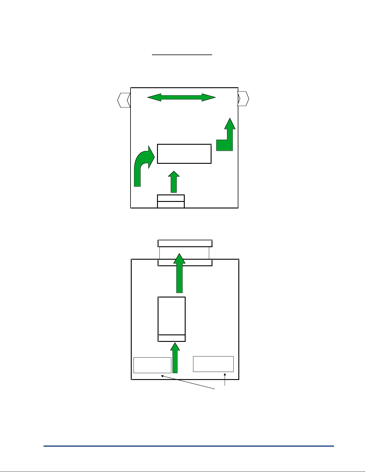
The forced air design of the MaxPac series allows mounting in any direction. It is essential that air flow through
the enclosure be planned to insure proper cooling.
The 100 amp through 300 amp open design MaxPac allow the input line power to connect from either of two directions.
The output power can only be connected from one direction. The three mounting configurations
are shown below (MaxPac II Three-Phase Two-Leg Shown).
Open designs above 300 amps and all closed designs allow incoming
and outgoing wiring in either direction.
In In
Configuration One
Cool Air In Warm Air Out
Fan Phase 1 Phase 3
or In Out or In Out
Configuration Two
Out Out
In In
Warm Air Out Cool Air In
Phase 1 Phase 3 Fan
or In or In
Configuration Three
Warm Air Out
Out
Phase 3
or In
In
Out
Phase 1
In or In
Fan
Cool Air In
- 7 -
© 2002 Chromalox®, Inc.1-888-996-9258
Installation Section
(
continuation of
p
a
g
e 5
)
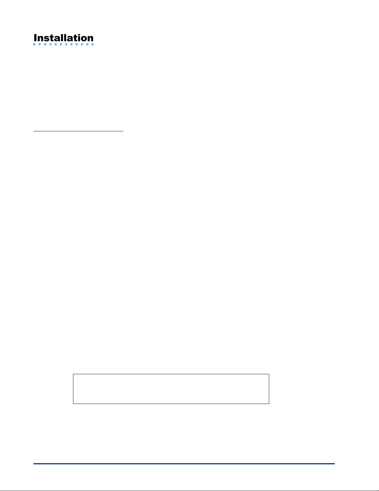
Examples of Proper Air Flow
Pagoda Top
Fan
Air
Louvers Louvers
MaxPac
Air
Fan MaxPac
Fan
Enclosure
Air Enclosure
Fan
Filter
Forced Air In
Forced Air Out
Louvers
Since hot air rises naturally, it is not recommended that cooling air ente
r
from the top and exhaust at the bottom of the enclosure.
- 8 - © 2002 Chromalox®, Inc. 1-888-996-9258
FigureFigure
FigureFigure
Figure Drawing NumberDrawing Number
Drawing NumberDrawing Number
Drawing Number ModelModel
ModelModel
Model
FigureFigure
FigureFigure
Figure ModelModel
ModelModel
Model
1 .............. 100A, 150A, & 200A 2-Leg Open Type
1 .............. 100A, 150A, 200A, & 300A 1-Leg Open Type
2 .............. 100A, 150A, & 200A 3-Leg Open Type
3 .............. 300A 2-Leg Open Type
4 .............. 100A, 150A, 200A, 300A & 400A 1-Leg Touch-Safe
4 .............. 400A 1-Leg Open Type
5 .............. 100A, 150A, 200A, 300A & 400A 2-Leg Touch-Safe
5 .............. 400A 2-Leg Open Type
6 .............. 100A, 150A, 200A, 300A & 400A 3-Leg Touch-Safe
6 .............. 300A & 400A 3-Leg Open Type
7 .............. 550A & 650A 1-Leg Touch-Safe
7 .............. 550A & 650A 1-Leg Open Type
8 .............. 550A & 650A 2-Leg Touch-Safe
8 .............. 550A & 650A 2-Leg Open Type
9 .............. 550A & 650A 3-Leg Touch-Safe
9 .............. 550A & 650A 3-Leg Open Type
................ 800-1200 Amp uni s, consul fac ory
4
○○○○○○○○○○○○
Installation
Please read all informa ion in his sec ion before beginning he ins alla ion of your MaxPac.
Ins alla ion of he MaxPac requires hree s eps:
1. Moun ing
2. Power wiring
3. 120 or 230 Vac 50/60hz for ins rumen power. See 4.2.4, pg. 16.
4.1 - Step 1: Mounting
Before moun ing your MaxPac, please read he sec ion i led “Before You Ins all’ on page 5 for a descrip ion of
an ideal environmen for he uni ’s opera ion.
The space required for moun ing he MaxPac Power Pak depends upon he model. The able below refers o
he figures on he following pages. These figures illus ra e he dimensions and moun ing holes for he various
MaxPac Power Pak models. Please refer o hese figures before moun ing your uni .
IMPORTANT: Please no e ha he figures on he following pages are
not drawn to the same scale.

- 9 -
© 2002 Chromalox®, Inc.1-888-996-9258
Figure 1 Figure 2
Figure 3 Figure 4
Figure 5
4.7" [107mm]
0.0" [0mm]
1.0" [25mm]
4.75" [121mm]
8.5" [216mm]
9.5" [241mm]
6.0" [153mm]
7.3" [185mm]
FIRING PACKAGE
FAN END
Ø0.280" [Ø7.11mm]
(6 HOLES)
4.2" [107mm]
0.0" [0mm]
1.0" [25mm]
7.2" [184mm]
13.5" [342mm]
14.5" [368mm]
6.0" [153mm]
7.28" [185mm]
FIRING PACKAGE
FAN END
Ø0.280" [Ø7.11mm]
(6 HOLES)
7.2" [183mm]
0.0" [0mm]
1.3" [33mm]
7.3" [185mm]
13.3" [337mm]
14.6" [371mm]
12.0" [305mm]
13.3" [338mm]
FIRING PACKAGE
FAN END
Ø0.280" [Ø7.11mm]
(6 HOLES)
5.12" [130mm]
0.0" [0mm]
1.3" [33mm]
9.3" [237mm]
13.3" [338mm]
14.6" [371mm]
8.1" [206mm]
9.1" [232mm]
FIRING PACKAGE
FAN END
Ø.3125 [Ø7.94mm]
(8 HOLES)
5.3" [135mm]
8.4" [214mm]
0.0" [0mm]
1.3" [33mm]
9.3" [237mm]
13.3" [338mm]
14.6" [371mm]
14.7" [375mm]
15.75" [400mm]
FIRING PACKAGE
FAN END
Ø.3125" [Ø7.94mm]
(8 HOLES)
5.3" [135mm]
Indice
Altri manuali Chromalox Sistema di controllo


