Columbus Instruments Rotamex-5 Manuale utente

Rotamex-5
0254-0001 v1.11
August 14, 2023
950 North Hague Ave.
Columbus, Ohio 43204-2121 USA
www.colinst.com
Phone: +1.614.276.0861
Fax: +1.614.276.0529
Toll Free: +1.800.669.5011

2
Rotamex-5 0254-0001 v1.11

Rotamex-5 0254-0001 v1.11
3
Table of Contents
1 –Introduction .....................................................................................................................................................................................................4
1.1System Overview........................................................................................................................................................................................4
1.2 System Specifications ...............................................................................................................................................................................4
2 –Hardware Installation.....................................................................................................................................................................................5
2.1 Changing Rod Assembly...........................................................................................................................................................................5
2.2 Mouse Rod Assembly ...............................................................................................................................................................................6
2.3 Rat Rod Assembly......................................................................................................................................................................................6
2.4 Sensor Adjustment ....................................................................................................................................................................................7
2.5 Detector and Sensor Cable Connection Guide ...................................................................................................................................8
2.6 Modified Sensor Bracket Setting Guide............................................................................................................................................. 10
3 –Controller ...................................................................................................................................................................................................... 14
3.1 Controller Hardware Connections ...................................................................................................................................................... 15
3.2 Controller Keypad .................................................................................................................................................................................. 16
3.3 Startup Menu........................................................................................................................................................................................... 17
3.4 Main Menu............................................................................................................................................................................................... 17
3.5 Experiment Setup Menu ....................................................................................................................................................................... 18
3.6 Run Experiment....................................................................................................................................................................................... 19
3.7 Diagnostics............................................................................................................................................................................................... 20
4 –Software ........................................................................................................................................................................................................ 21
4.1 Installation................................................................................................................................................................................................ 21
4.2 Connecting Interface Box ..................................................................................................................................................................... 21
4.3 Running Software................................................................................................................................................................................... 22
4.3.1 Communication Port Setup.......................................................................................................................................................... 23
4.3.2 Scanning for Configured Devices ............................................................................................................................................... 23
4.4 Menus ....................................................................................................................................................................................................... 24
4.4.1 Experiment Menu........................................................................................................................................................................... 24
4.4.2 Diagnostic Menu ............................................................................................................................................................................ 26
4.5 Running Experiment............................................................................................................................................................................... 27
4.6 Experiment Data..................................................................................................................................................................................... 29
4.6.1 Passive Rotation Mode ................................................................................................................................................................. 30
4.6.2 Data File Format............................................................................................................................................................................. 31

Rotamex-5 0254-0001 v1.11
4
1 –Introduction
1.1 System Overview
The Columbus Instruments Rotamex-5 System provides an automated approach to rotarod measurements. It can operate
with rats or mice and up to 4 subjects. The main unit is equipped with four lanes and a control unit. The rotarod unit has
individually divided areas on the rotarod spindle within which the subjects are contained. The rotational speed of rotarod
spindle is controlled by system software. Infrared beams are used to detect when a subject has fallen from the rotarod. The
sensors discriminate between the animal's tail and body thereby eliminating any erroneous indications of a subject fall that
may be caused by the subject's tail. When the subject has fallen from the rotarod, the system logs this as the end of the
experiment for that particular subject. Information such as the total time running on the rotarod (Time Running), and the
Rotarod's current speed at the time of the subjects fall are recorded. All experiment setup parameters are also recorded.
Rotamex-5 can be used as a stand-alone device or it can be interfaced through an RS232 communication port to Windows
compatible computer for storing data for later review or importation into a third party statistical analysis program.
1.2 System Specifications
Number of Exercise Lanes: 4
Rotarod Spindle Speed Range: 0 - 99.9 RPM
Acceleration Increments: 0.1 RPM per second. to 20.0 RPM per second
Mouse Spindle Dimensions: 3.0 CM x 9.5 CM
Rat Spindle Dimensions: 7.0 CM x 9.5 CM
Fall height From Rod Center: 44.5 CM
Unit Dimensions (LxWxH): 61cm X 56cm X 77cm
Weight: 27.5 kg
Data Recorded: Running duration, Rotarod speed at time of fall
Animal Detection Method: Scanning infrared beam(32) sensors monitor animals absence from rod assembly.
Power Connections: 100 Vac to 240 Vac @ 50-60 Hz Auto configurable.
Power Consumption: 70 Watts
Fuse size: 3 amp slow blow
Communication (optional): RS-232 to RS422(CIBUS) Multi drop. (Max of 16 devices)
Rotamex-5 0254-0001 v1.11
5
2 –Hardware Installation
The Rotamex-5 comes pre-assembled from the factory with either a standard mouse or rat rod assembly. There is no need for
additional assembly. The instrument should be placed on a flat study surface. If the optional lid assembly was purchased
ensure that there is enough room for the lid assembly to open to allow easy placement of animals on the units rod assembly.
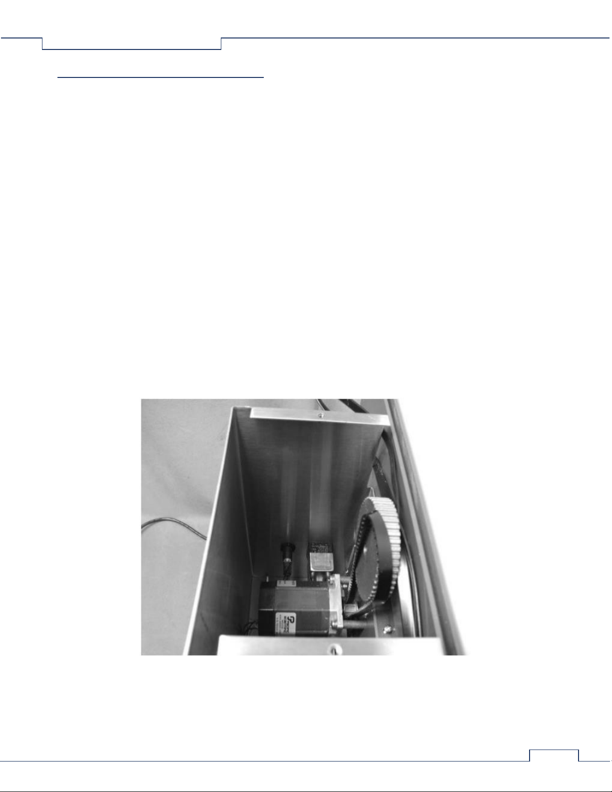
2.1 Changing Rod Assembly
The Rotamex-5 can be used with either 3.0cm(mouse) or 7.0cm(rat) rod assembly. The rod assembly is designed to allow the
end user to change from rod assemblies quickly and easily without the need for speed recalibration. The procedure for
changing the rod assembly can be found below.
1. First ensure that the power is turned off and the system is unplugged from the power source.
2. If the optional Lid assembly was purchased remove the lid assembly for lifting straight up the side walls.
3. Remove the motor compartment lid assembly. This is accomplished by removing the two Phillips head screws.
4. Remove the belt assembly from the top geared pulley. To easy removal of belt simply pull outward on the belt while
the rod is slowly rotated by hand. This action is very similar to removing a chain on a bicycle. This should be
performed slowly to prevent fingers from getting pinched between the belt assembly and pulley.
5. Once the belt is removed the complete rod assembly can be removed by lifting straight up on the side rod holders.
6. Once the Rod assembly has been removed simply install the new rod assembly onto the Rotamex side panels.
7. To install the belt assembly on the geared pulley, simply slide the belt on the front of the pulley while rotating the
rotarod assembly backwards. Once the belt is started, continue rotating the Rod assembly backwards until the belt is
fully seated. This action is very similar to installing a chain on a bicycle. This should be performed slowly to prevent
fingers from getting pinched between the belt assembly and pulley.
8. Reinstall the motor compartment lid assembly and securing the two Phillips screws.
9. If the option Lid assembly was purchased attach it to the top of the rod holder assemblies.
10. Reconnect power to the system and turn the switch on.
Rotamex-5 0254-0001 v1.11
6
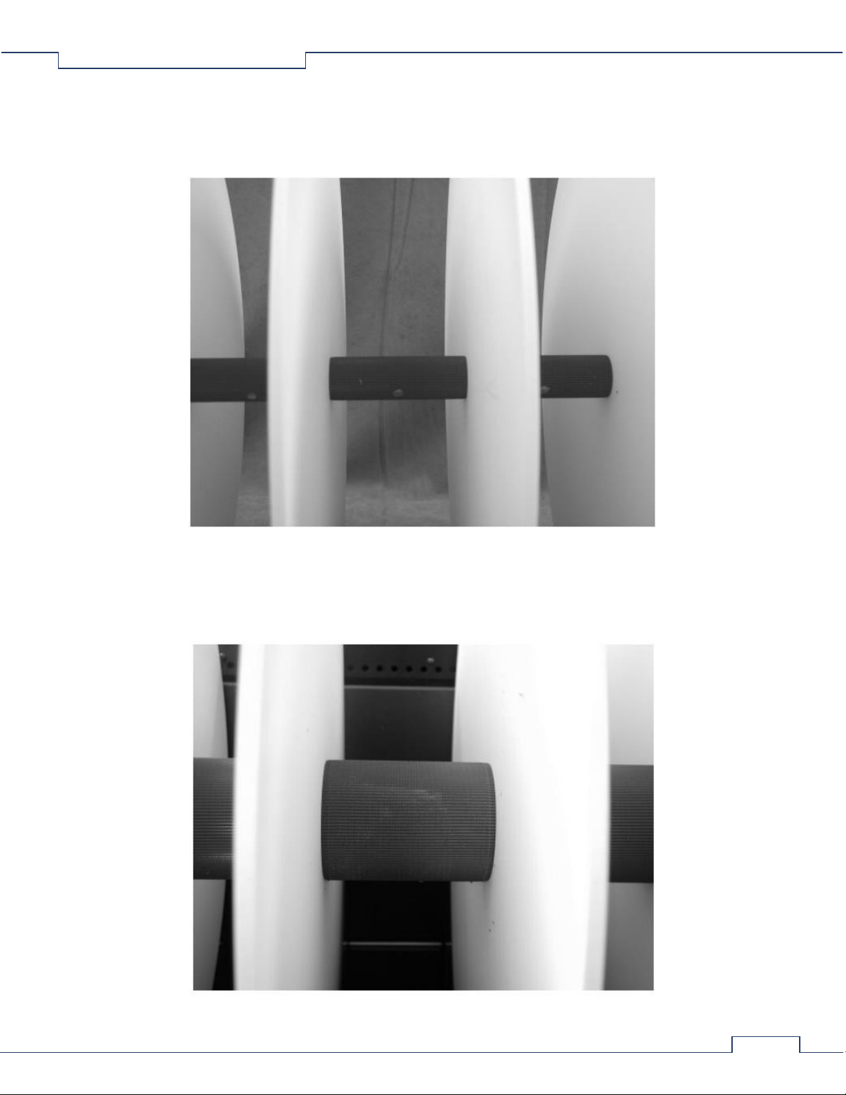
2.2 Mouse Rod Assembly
The Rotamex-5 can be configured with a smaller rod assembly that has a 3.0 cm rod diameter. This is the preferred rod when
running smaller animals such as mice. The width of the running surface is approximately 9.5 cm. The rod surface is
constructed from grey PVC with a knurled finished.
2.3 Rat Rod Assembly
The Rotamex-5 can be configured with a rod assembly that has a 7.0 cm rod diameter. This is the preferred rod when running
larger animals such as rats. The width of the running surface is approximately 9.5 cm. The rod surface is constructed from
grey PVC with a knurled finished.
Rotamex-5 0254-0001 v1.11
7
2.4 Sensor Adjustment
The Rotamex-5 incorporates a 32-beam optical sensor mounter slightly over the rotarod assembly. This approach allows for
more precise detection of when the animal leaves or falls from the rod assembly. This method also allows for detection of the
animal gripping the rod assembly and rotating along with the rod as it spins. Since there are two different rod diameters the
sensor beams will need to be adjusted for each.
Beam Adjustment for Mouse Rod assembly. When using the mouse rod assembly (3.0 cm) the sensors will need to be
adjusted to the lowest position on the sensor bracket. When adjusting the sensors ensure that both emitter and detector are
positioned on the same bracket position.
Beam adjustment for Rat Rod Assembly. When using the Rat Rod assembly (7.0 cm) the sensors will need to be adjusted to
the highest position on the sensor bracket. When adjusting the sensors ensure that both emitter and detector are positioned
on the same bracket position.
Rotamex-5 0254-0001 v1.11
8
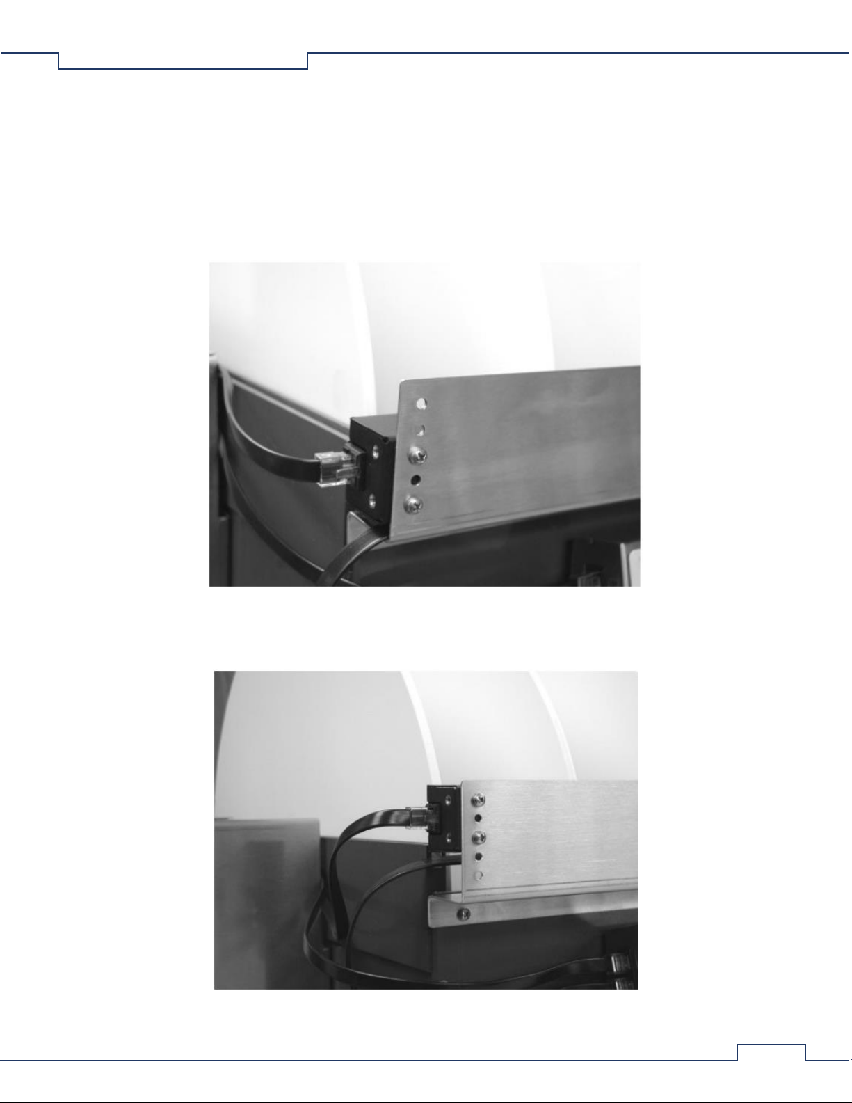
2.5 Detector and Sensor Cable Connection Guide
The following is a guide for connecting the RJ45 cables to the emitters and detectors to the front controller.
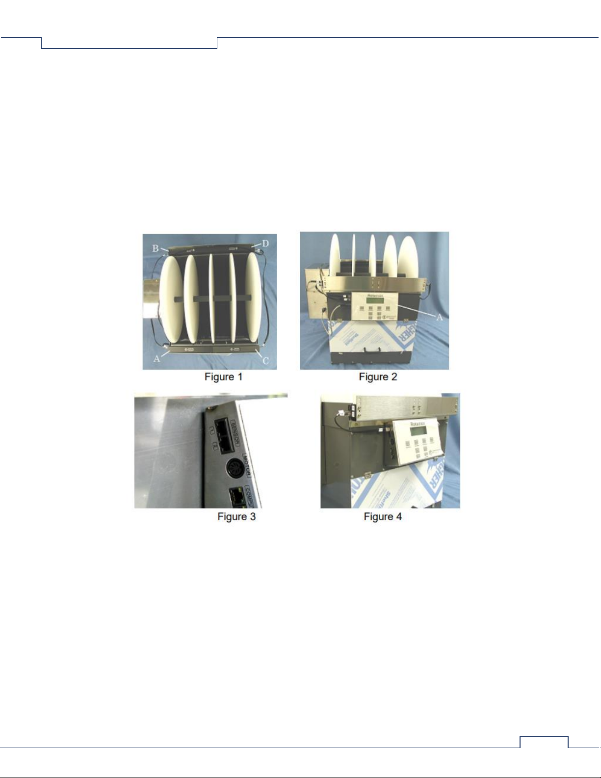
Controller and Sensors
The front detector (figure 1, item A) is located on the left side, and its associated emitter (figure 1, item B) is located directly
across from it on the rear. The front emitter (figure 1, item C) is located on the right side, and its associated detector (figure 1,
item D) is located directly across from it on the rear. The controller is located on the front upper panel of the enclosure (figure
2, item A). The connectors marked "Sensor" on the controller (figure 3) are used for connecting the detectors to the
controller. Four interconnecting cables are used for connecting the emitters and, detectors to the controller. Both connectors
on each cable are marked with a number that corresponds to a number at a connector on one of the emitters or detectors or
the controller.
Rotamex-5 0254-0001 v1.11
9
Sensor Cable Installation
Both plug ends on each cable have an assigned number that matches the number assigned to a particular jack on the
detectors, emitters, and controller. Cable installation is made simple by matching the numbers on the plugs with the numbers
on the jacks.
1. CABLE 1/3: insert plug number 1 into the number 1 "Sensor" jack on the controller (figure 4). Insert plug number 3
of the same cable into jack number 3 of the front detector (figure 4).
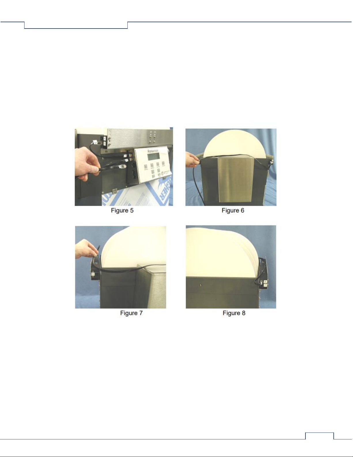
2. CABLE 2/6: insert plug number 2 into the number 2 "Sensor" jack on the controller (figure 5). Lay the cable over the
top of the motor enclosure and lay it over the top of the rear emitter and detector (figures 6 and 7). Insert plug
number 6 of the same cable into the number 6 jack on the rear detector (figure 8). Note 1: this cable can also be laid
over the top of the front detector and emitter and ran to the rear detector if this installation is more desired. Note 2:
ensure that when laying the cable over the detector and emitter that it does not block the windows of either sensor.
Rotamex-5 0254-0001 v1.11
10
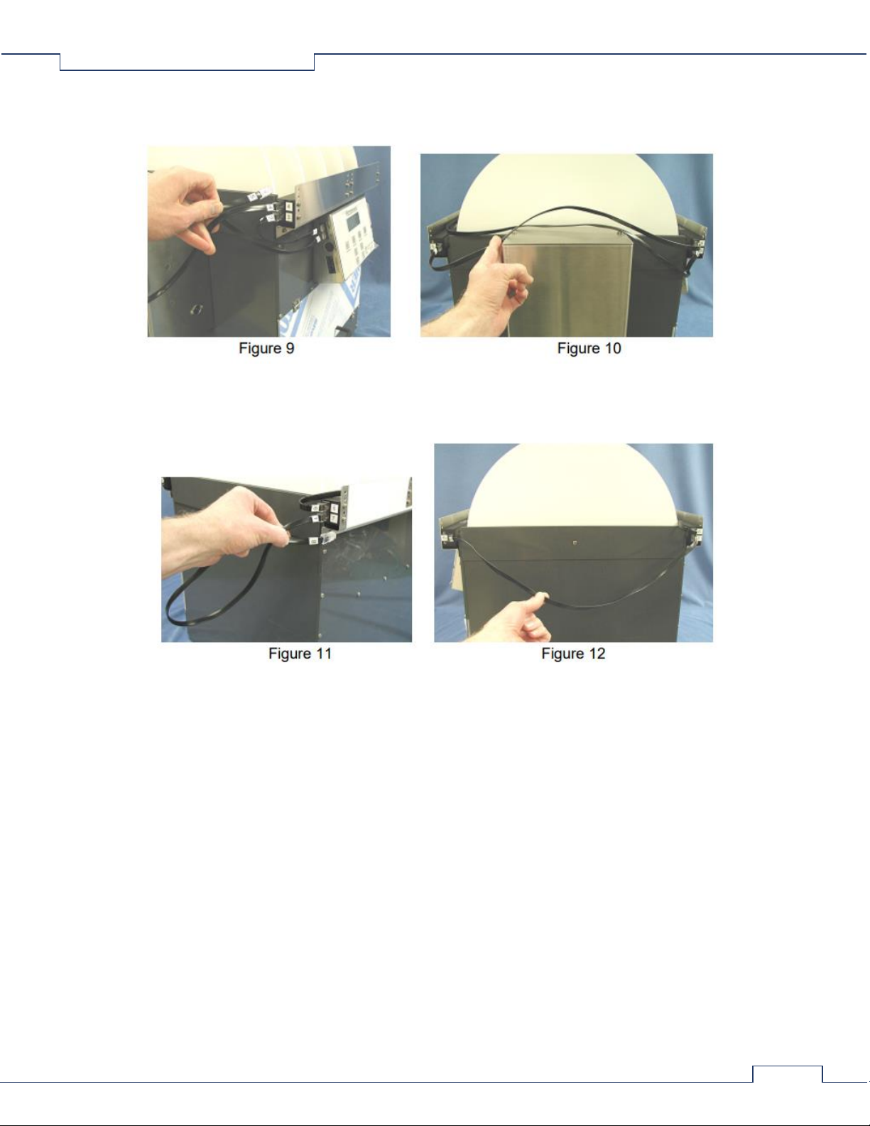
3. CABLE 4/5: insert plug number 4 into the number 4 jack on the front detector (figure 9). Lay the cable over the
motor enclosure and insert plug number 5 of the same cable into the number 5 jack on the rear emitter (figure 10).
4. CABLE 7/8: insert the number 7 plug into the number 7 jack on the rear detector (figure 11). Insert plug number 8 of
the same cable into the number 8 jack on the front emitter (figure 12).
2.6 Modified Sensor Bracket Setting Guide
Modified Sensor Brackets
The modified sensor brackets have additional settings for adjusting the height of the sensors for both mouse and rat
configurations. As shown in the Rotamex-5 Instruction manual on page 8, the mouse position set the detection beam 1/4
inches above the rod. The bracket shown is the original bracket with five mounting holes. The holes are numbered from one
through five with number one at the bottom hole. The modified bracket has an additional mounting hole inserted between
the original number two and three holes. So the holes are renumbered from one to six. See figure 1, group A. The modified
bracket has an additional mounting hole on the lower mounting plate (see figure 1, group B) which allows the bracket to be
lowered by 1/4 inch. To set the height of the bracket at the lower height, mount the bracket to the enclosure at mounting
hole "A" as shown in figure 1. Mounting hole "B" is used to set the bracket height higher by 1/4 inches from the lower
position.
Indice
Altri manuali Columbus Instruments Strumento di misura


