Continental Refrigerator E-Access WI2427LF Manuale utente

Continental E●Access Control Systems
Installation Instructions
for 1 Door Systems
Document Number: 100116-CAE
Installation Instructions for 1 Door Systems – November 2022 Page 1
Reference: WI242 LF

Table of Contents
Notifications
Approvals....................................................3
Notice.........................................................3
Introduction
Access Control Overview...........................4
System Overview........................................4
System Specifications
Installation of 1 Door Systems
Installation Check List.................................6
Locating the Controller for Installation........6
Mounting 1DC Systems
Controller Features – 1 Door Systems
Controller Inputs.........................................8
Controller Wiring Harnesses.......................9
Input Wiring..............................................10
14 Pin Reader Harness............................10
Controller Outputs & Power Input.............14
Output Wiring Requirements....................15
10 Position Power Harness......................15
Powering On and Connecting to a Network
Preparing for the Network.........................1
Connecting to the Network.......................19
Adding Clients to Systems........................19
Smart IP Finder........................................21
Trouble Shooting
Testing, Maintenance and Service
Parts List
Contact & Warranty Information
Installation Instructions for 1 Door Systems – November 2022 Page 2

Notifications
Copyright
Copyright © 2022, all rights reserved. No part of this document may be reproduced, copied,
adapted or transmitted in any form without written permission.
Approvals
This equipment has been tested and found to comply with the limits for a Class A digital device,
pursuant to part 15 of the FCC Rules. These limits are designed to provide reasonable
protection against harmful interference when the equipment is operated in a commercial
environment. This equipment generates and can radiate radio frequency energy and if not
installed and used in accordance with the manual, may cause harmful interference. Operation of
this equipment in a residential area is likely to cause harmful interference in which case the user
will be required to correct the interference at their own expense.
This Access Control System is compliant with Level I UL 294 listed devices and must be
installed in a secure, controlled location.
Notice
This manual contains information regarding the basic installation and configuration of the
browser-based Access Control System. It must be read and completely understood before
installation or operation.
It is intended that this unit will be installed by persons trained and qualified to install access
control systems and has the skills and knowledge working with electrical circuits and safety
codes. Important safeguards and instructions in this manual cannot cover all possible situations
and conditions that occur during installation and use and it must be understood that common
sense and caution must be exercised by the person(s) installing, maintaining and operating the
equipment.
Installations must conform to all national and local building and electrical codes.
This manual is for installing 1 Door Systems;
Model 1DC.
Installation Instructions for 1 Door Systems – November 2022 Page 3

ntroduction
Access Control Overview
Access Control is the selective restriction to a place or resource such as a property, building or
room to authorized persons and is a matter of who, where, and when. An access control system
is used to automate access control using credentials, credential readers, electric door locks and
other devices. Administrators configure the system to determine who is allowed to enter or exit,
where they are allowed to exit or enter, and when they are allowed to enter or exit. When access
is granted, the door is unlocked for a predetermined time and transaction is recorded. When
access is denied, the door remains locked and the attempted access is recorded. Administrators
can then run reports on the recorded transactions to review activity for selected dates and times.
System Overview
Controller models are available in variety of configurations starting from 1 Door models that
require a separate power supply to 2 & 4 Door models that include an integrated power supply
for the controller and door lock power. Most models can be ungraded after installation with
enhanced features, such as enhanced reporting or more users, using software license keys. All
controllers include tamper and power fault inputs, in and out readers, request to exit and door
position inputs for each door and auxiliary inputs and outputs. All controllers are designed to be
connected to a network using an Ethernet RJ45 connector and configured using the integrated
web server.
Controllers can be configured as either a server or a client. All systems require a server
controller. Some systems have the ability to add additional client controllers to increase the
number of doors, inputs or outputs or control elevators. The software license key is used by the
controller to determine if it is a server or a client. After logging in, the license information about a
can be determined by clicking on the license icon at the bottom of the web page.
Certain models offer a mobile APP that can be used to setup and configure, view logs, lock and
unlock doors and activate threat levels. In addition, some systems also offers a cloud service
that provides a portal where a users or dealer can log into and manage one or many systems
securely.
Client controllers communicate with the server controller via the local area network and are
configured through the server using a web browser on PC connected to the network. Once the
server or client controller is configured, they will function without a network connection or the
PC. The network and PC is only required for setup, configuration and reporting.
Installation Instructions for 1 Door Systems – November 2022 Page 4

System Specifications
General Specifications
Operating System Embedded Linux
Transactions > 60 per Second
Power Requirements (excluding door locks) Regulated 12VDC @ 2A, Class 2 (not supplied)
Operating Temperature 50ºF to 95ºF (10ºC to 35ºC)
Plastic Enclosure Size (W x H x D) 3.2 x 3.0 x 1.3 in (81 x 8 x 32 mm)
Metal Enclosure Size (W x H x D) 4.25 x 4.25 x 2.0 in (108 x 108 x 50mm)
Model 1DC & 1DM
Standby Power Requirement 350mA @ 12V
Number of Doors 2 Total, One In & One Reader
Readers (Wiegand) 2 Total, One In & One Out Reader
Reader Power 300 mA @ 12V Max per Reader
600 mA @ 12V Max per System
Request to Exit (REX) Input 1
Door Position (status) Input 1
Auxiliary Input 1
Tamper Digital Input 1
Power Fault Digital Input 1
Door Lock Output 1 Form C Relay, 24V @ 1.0A
Auxiliary Output 1 Form C Relay, 24V @ 1.0A
UL294 7th Edition Rating
Destructive Attack Line Security Endurance Standby Power
Single Point
Locking Device
with Key Locks
Level I Level I Level IV Level I Level I
Installation Instructions for 1 Door Systems – November 2022 Page 5

nstallation of 1 Door Systems
nstallation Check List
The list below provides a logical sequence for installing a system. This list cannot cover all
possible situations and conditions that occur during installation and use and it must be
understood that common sense and caution must be exercised by the person(s) installing,
maintaining and operating the equipment.
✔Calculate the systems power requirement by adding up the power required
for each device connected to the system to make sure the required power
can be provided by the system.
✔Mount the controller in a secure, controlled location
✔Connect the inputs and outputs
✔Connect the readers
✔Connect the door locks and auxiliary outputs
✔Connect power to the controller using a dedicated12 VDC, 2 AMP UL294B
listed power supply. Connect the power supply to an unswitched, grounded
outlet
✔Obtain an IP address, Subnet Mask, DNS and other information from the
network administrator
✔Configure the controller's network settings
✔Connect the controller to the local area network and apply license
✔Add optional license keys to upgrade features such as more doors, cloud-
based management, etc.
✔Turn on services such as mobile app, cloud-based management, backup,
time server, etc.
Locating the Controller for nstallation
Choose a centrally located, secure, clean and dry area near an AC power source. Avoid
mounting the controller within 6 feet of any equipment that may generate electrical interference.
NOTICE: The power supply used for the controller must only
be connected to an unswitched grounded 115 VAC outlet. If
an unswitched outlet is not available or within 5 feet of the
controller mounting location have a licensed electrician install
an outlet per local codes. All wiring must be in accordance with
the National Electrical Code NPFA 70 and all local codes. For
UL installations the maximum Ethernet cable length is 98.5
feet (30 meters).
NOTE: This device complies with Part 15 of the FCC Rules.
Operation is subject to the following two conditions: (1) this
device may not cause harmful interference and (2) this device
must accept any interference received including interference
that may cause undesired operation.
Installation Instructions for 1 Door Systems – November 2022 Page 6
Mounting 1DC Systems
Using the provided mounting bracket, the 1 door controller can be mounted vertically or
horizontally in a UL listed enclosure with an integrated tamper switch, that is located in a secure
location. The aluminum heat sink should face away from the mounting surface with a minimum
of 1 inch (25.4 mm) of clearance above the heat sink. The temperature in the mounting location
must be within the system's specified limits. When running wires through knockouts in
enclosures, install bushings or conduit connectors as needed to protect wires from damage.
1. Run all wires to the controller's location and label the wires according to their use.
2. Locate the enclosure for the 1 door controller on the wall and level. Mark the mounting
holes on the wall and remove the enclosure and install anchors appropriate for the type
of wall and mounting conditions.
3. DO NOT DR LL the mounting holes while the enclosure is in place on the wall. Dust and
debris from drilling will contaminate and damage the electronics.
4. Partially insert mounting screws into the top two mounting holes and hang the enclosure
on the screws. Check for level, insert the lower screws and tighten all four mounting
screws.
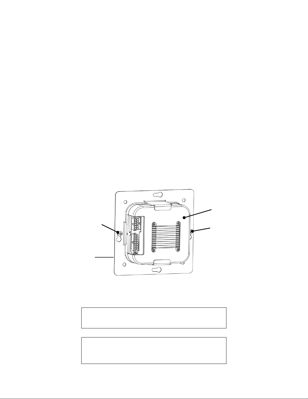
5. Using the provided mounting bracket as a template, locate the bracket in the enclosure
and mark the location of the mounting screws. The keyholes in the bracket are sized for
#6 pan head self taping screws. Drill the holes for the mounting screws and partly thread
the screws into the holes. Clean any debris from drilling to prevent damage to the
electronics. Place the controller into the mounting bracket and hang on the mounting
screws. Check for level and tighten the mounting screws.
6. Run the wires through the knockout holes and connect to the appropriate harnesses (see
following sections of the manual for wiring details).
. Connect the tamper switch to the controller's tamper inputs.
NOTICE: This equipment includes electronic components that
are sensitive to static electricity. Make sure to discharge by
touching an earth ground before handling this equipment.
NOTE: When locating the controller choose a centrally located
secure clean and dry area. Avoid mounting the controller within
6 feet (2 meters) of any equipment that generates electrical
interference.
Installation Instructions for 1 Door Systems – November 2022 Page
#6 Mounting
Screw
#6 Mounting
Screw
1 Door
Controller
Mounting
Bracket
1 Door
Controller

Controller Features – 1 Door Systems
The following shows the controller's features and wiring components.
Controller nputs
Controllers can monitor door position, request to exit and auxiliary (general purpose) inputs. All
inputs are assigned default states that can be modified as needed through the user interface.
The table below shows the default state for each of the inputs.
nput Type Default State
Door Position (status) Inputs Disabled
Request to Exit Inputs Normally Open, Momentary, Unsupervised
Auxiliary Inputs Normally Open, Momentary, Unsupervised
Tamper Normally Open, Momentary, Unsupervised
Power Fault Normally Open, Momentary, Unsupervised
Installation Instructions for 1 Door Systems – November 2022 Page 8
HEAT SINK
ETHERNET
*HARDWARE
RESET
*IP RESET
*FACTORY
DEFAULT
POWER
HARNESS
CONNECTOR
READER
HARNESS
CONNECTOR
USB – FOR
DATA BACKUP
DEVICE ONLY

nput Circuit Configurations
The table below shows the different input configurations. These types can be independently
configured for each input by the user.
Unupervised Unsupervised
Normally Open Normally Open
Note: Use 1K Ohm Resistor
Normally Closed Normally Closed
Controller Wiring Harnesses
The controller is provided with two plug-in wiring harnesses for connecting field wiring. The
harnesses are color coded and marked with labels to indicate the proper connection for field
wiring.
The Minimum Cable Specifications for the wiring of inputs is
22 AWG Belden or equivalent with a maximum distance of
2000 feet (610 meters).
NOTE: All wiring shall conform with the National Electrical
Code NPFA70 and local building codes.
Installation Instructions for 1 Door Systems – November 2022 Page 9
nput Wiring
All inputs may be configured for normally open or normally closed contacts. Door position,
request to exit and auxiliary inputs may also be configured with for supervision to detect if wiring
to the contact is broken or cut. Wires must not be route in parallel with or in the same
con uit with any high voltage AC wiring.
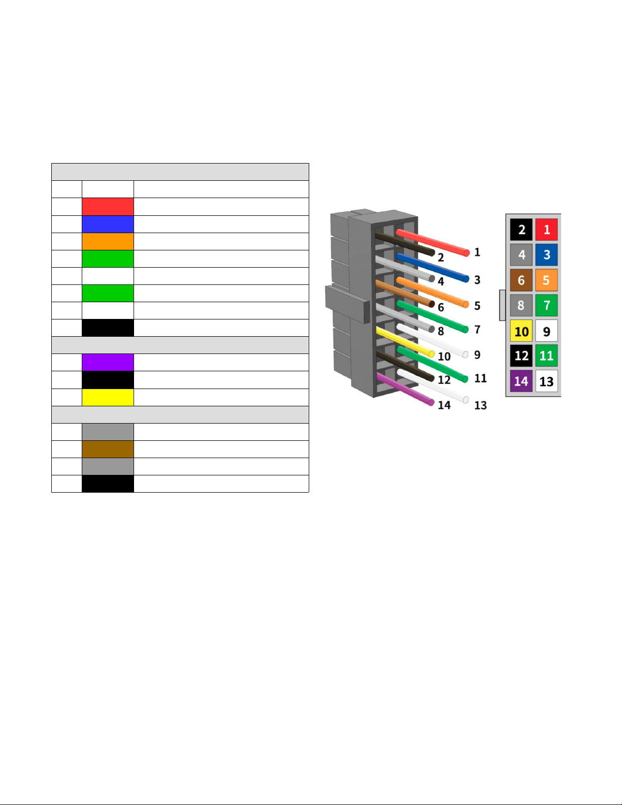
14 Pin Reader Harness
nput Power
PIN Color Description
1RED +12 VDC Power for In & Out Readers
3BLUE LED, In & Out Readers
5ORANGE Buzzer, In & Out Readers
GREEN D0, In Reader
9WH TE D1, In Reader
11 GREEN D0, Out Reader
13 WH TE D1, Out Reader
2BLACK Ground, In & Out Readers
Door nputs
14 PURPLE Door Position Input
12 BLACK Ground
10 YELLOW Request to Exit Input
System nputs
8GRAY AUX Input
6BROWN Tamper
4GRAY Power Fault
12 BLACK Ground
Installation Instructions for 1 Door Systems – November 2022 Page 10
Indice


