
Cosmos XP-3180 Manuale utente

Oxygen Indicator
Instruction Manual
This instruction manual explains to the use of two models listed on the left
●Please keep this instruction manual available for quick reference when
needed
●Before use, carefully read this instruction manual and fully understand the
content.
■XP-3180
■XP-3180E
(For combustion management)
Specifications No.: XP-3000T

Table of Contents
Contents of This Package …………………………………………… 1
1. Introduction ………………………………………………………… 2
Explosion-proof Precautions ………………………………………………………………………………… 2
Explanation of Symbols ……………………………………………………………………………………… 2
Safe Operation ………………………………………………………………………………………………… 3
2. Component Names and Functions …………………………… 4
3. Operating Procedure ……………………………………………… 8
Procedure ……………………………………………………………………………………………………… 8
Gas Alarm ……………………………………………………………………………………………………… 10
Functions and Settings Methods……………………………………………………………………………… 11
Peak Hold Settings …………………………………………………………………………………………… 12
Alarm Buzzer Silence Settings ……………………………………………………………………………… 13
Logging ………………………………………………………………………………………………………… 14
Data Logger Communications Screen ……………………………………………………………………… 15
Time Settings …………………………………………………………………………………………………… 16
4. Error Message (Malfunction Alarm) …………………………… 17
5. Replacement of Consumable Parts …………………………… 18
Filter Element Replacement…………………………………………………………………………………… 18
Battery Replacement ………………………………………………………………………………………… 19
Sensor Unit Replacement …………………………………………………………………………………… 20
6. Maintenance Inspection ………………………………………… 22
Daily Inspection ………………………………………………………………………………………………… 22
Regular Inspection……………………………………………………………………………………………… 22
Main Replacement Parts ……………………………………………………………………………………… 22
7. Troubleshooting …………………………………………………… 23
8. Warranty …………………………………………………………… 24
9. Specifications ……………………………………………………… 25
10. Markings of explosion-proof …………………………………… 26
11. Detection Principle ………………………………………………… 27
12. Glossary …………………………………………………………… 27

−1−
-Unpacking-
The following standard components are packed together with the Gas Detector. Carefully check the
contents against the list when unpacking. If any components are missing or damaged, contact your
New-Cosmos Electric representative. A replacement for the missing or damaged component will be
sent to you.
Optional items (separately sold)
*A PC satisfying the following conditions is required.
OS: MS-Windows(R) XP
(Gas Detector operation has not been confirmed in other OS versions.)
Hard disk: Free space of 20 Mbytes or more
CD-ROM drive: A CD-ROM drive capable of reading CD-R data
(The software is provided in a CD-R disc.)
USB port: A USB1.1 or higher grade port available to Windows, which allows
connection with connector type A.
Portable Gas Detector
(with carrying case) 1
Shoulder belt 1
AA alkaline batteries (Toshiba LR6) 4
Instruction Manual 1
Warranty 1
Inspection report 1
Operating instruction card 1
1-m gas sampling hose (with drain filter and suction pipe)for XP-3180 1
Two spare filter elements (FE-2)for XP-3180 1
Cooling drain filter set (with cooling drain filter and cooling pipe) for XP-3180E 1
Two spare filter elements (FE-10) for XP-3180E 1
Log Data Collection Set *
Software (CD-R)
USB cable (1.8 m) provided
1

−2−
Introduction
Product Model Features
Gas Detector XP-3180 Digitally displays oxygen concentration (with
an automatic alarm turned ON at 18vol%).
Gas Detector for combustion
management XP-3180E Measures oxygen in flue gas (with an
automatic alarm turned ON at 18vol%).
Thank you for purchasing the XP-3000 series Oxygen Indicator. To ensure proper use, please read this
operation manual thoroughly before using the product to prevent gas accidents and oxygen deficiency
accidents, and to conduct maintenance inspections.
Be sure you fully understand this manual regardless of whether you have used a Gas Detector before or
not. Do not use the product in ways not described in the manual.
The following two types of XP-3000 series Composite Gas Detectors are available.
1. Introduction
Operating conditions:
●Replace batteries only in area know to be NON-HAZARDOUS.
●Use the Gas detector in the carrying case specified by New-Cosmos Electric.
●As a comprehensive measure for the prevention of danger resulting from static electricity.
It is desirable for the user carrying the Gas Detector to wear antistatic clothing and
electrically conductive shoes(antistatic work shoes). The floor should also be electrically
conductive( with an electrical leakage resistance of 10 MΩor less.)
●In the measurement of the oxygen density, do not use the Gas Detector for any mixtures
other than air mixed with combustible gas or steam mixed with toxic gas.
●Warning-Substitution of components may impair intrinsic safety
●Use only Panasonic LR6XJK, Toshiba LR6, or Duracell MN1500 batteries
●Warning-Do Not Replace Batteries when an explosive gas atmosphere may be present
●Warning-Potential Electrostatic Charging Hazard-Do not remove leather case in a hazardous
location
●Warning-Do not connect anything to the USB port when an explosive gas atmosphere may
be present(Um=5.5V)
■Explanation of Symbols
The following symbols are used for safety purposes:
■Explosion-proof Precautions
Follow the explosion-proof XXXXXXXXXX.
DANGER
WARNING
CAUTION
: Indicates a hazardous situation that, if not avoided, could result in serious
injury or death.
: Indicates a potentially hazardous situation that, if not avoided, could result
in serious injury or death.
: Indicates a potentially hazardous situation that, if not avoided, could result
in minor injury or physical damage.
: Indicates operational advice and/or instructions.
Note

−3−
Introduction
■Safe Operation
In order to use the Gas Detector safely, be sure to observe the following items.
*Special Instruction and Warning :
Use Panasonic LR6XJK, Toshiba LR6, or Duracell MN1500 batteries. Use of any other
manufacuturer or type will violate intrinsic safety requirement. Remove and replace the batteries
only in areas known to be non-hazardous.
1. Introduction (continued from previous page)
DANGER ●If the gas alarm turns ON, immediately take all necessary measures to
prevent Oxygen deficiency.
WARNING ●Be sure to turn ON the Gas Detector in clean air. Zero calibration (21vol%
calibration in the case of oxygen) is done automatically. Therefore, the
wrong gas concentration will be displayed if zero calibration is done in a
gas atmosphere.
●Do not close the suction port or exhaust port, or no gas detection will be
possible.
●Use the filter element in a clean state. Normal detection cannot be performed
if the filter element is dirty or moisture adheres to the filter element.
CAUTION ●Remove the batteries and store the Gas Detector if it is not to be used for a
long time.
●The Gas Detector has an explosion-proof construction. Do not
disassemble or modify the Gas Detector or change the structure or electric
circuits of the Gas Detector. Otherwise, the explosion-proof performance
of the Gas Detector will be damaged.
●Do not leave the Gas Detector in high-temperature or highly humid places,
or the performance of the Gas Detector may be adversely affected.
●Keep the Gas Detector away from radical temperature or humidity
changes, walkie-talkie, mobile phone, or its performance may be adversely
affected.
●Keep the Gas Detector away from great atmospheric pressure changes,
or the performance of the sensor may be adversely affected or the sensor
may be damaged.
●Do not drop, hit, or apply a strong mechanical shock to the Gas Detector,
or its performance may be adversely affected.
●The Gas Detector is not drip-proof but the leather case protects the Gas
Detector from water drips. Keep the Gas Detector away from water drips
as much as possible.
●Do not let the Gas Detector draw in water.
●Prolonged measurement of combustion exhaust gas will shorten the life of
the sensor. Do not use the sensor continuously for more than 20 minutes.
●High-density SO2 or Cl2 gas may shorten the life of the sensor or cause
considerable errors in the sensor.
●Do not use the Gas Detector under a pressure of two atmospheres or in
airplanes, or the Gas Detector may turn ON the alarm due to the change of
oxygen partial pressure.

−4−
Component Names and Functions
2. Component Names and Functions
No. Name Function
1 Alarm lamp Flashes at the time of gas alarming.
2 Gas sampling hose connection port Connects to the gas sampling hose.
3 Exhaust port Exhausts sampled gas.
4 Buzzer opening Sounds a buzzer.
5 Gas type seal Displays the model number and the types of detectable gases.
6 Battery cover The cover for the battery compartment.
7 USB connector Connects to a USB cable (optional item).
(6)
(7)
(3) (1) (2)
(9)
(4)
(5)
(10)
(11)

−5−
Component Names and Functions
No. Name Function
9
LCD main screen Displays gas concentration and a variety of messages.
A. Displays gas concentration.
B. Displays the unit of measurement.
C. Displays the remaining battery level.
D. Displays peak hold values if the peak hold
function is set.
E. Displays at the time of a gas alarm.
F. Indicates that the alarm buzzer sounds at the time
of a gas alarm.
G.Displays gas concentration in bar graph form.
H. Indicates that the Gas Detector is logging (saving
data in memory).
10
LCD sub screen Displays gas concentration and messages.
I. Indicates Time.
11
Control panel a. Used to turn the Gas Detector ON and OFF.
b. Used for automatic zero calibration.
c. Used to turn ON the backlight.
d. Used to stop the alarm buzzer.
• Used to make an alarm point check with the
button continuously pressed.
e. Used to make function settings.
2. Component Names and Functions (continued from previous page)
C D E
A
F
G
H
B
I
ac
d
e
b

−6−
Component Names and Functions
No. Name Function
1 Gas sampling hose Leads gas to the Gas Detector. (1 m long)
2 Coupler Connects to the Gas Detector.
3 Drain filter (DF-4) Prevents the penetration of water and dust into the Gas Detector.
The filter element (FE-2) is mounted.
4Suction attachment pipe (AT-3A) Gas suction port.
1-m gas sampling hose (for XP-3180)
2. Component Names and Functions (continued from previous page)
Cooling Drain Filter Set (for XP-3180E)
No. Name Function
1 Gas sampling hose Leads gas to the Gas Detector.
2 Coupler Connects to the Gas Detector.
3 Cooling drain filter Prevents the penetration of water and dust into the Gas Detector.
The filter element (FE-10) is mounted.
4Cooling pipe Gas suction port.
(2)
(1)
(3) (4)
(3) (4)
(1)
(2)
−7−
Component Names and Functions
2. Component Names and Functions (continued from previous page)
No. Name Function
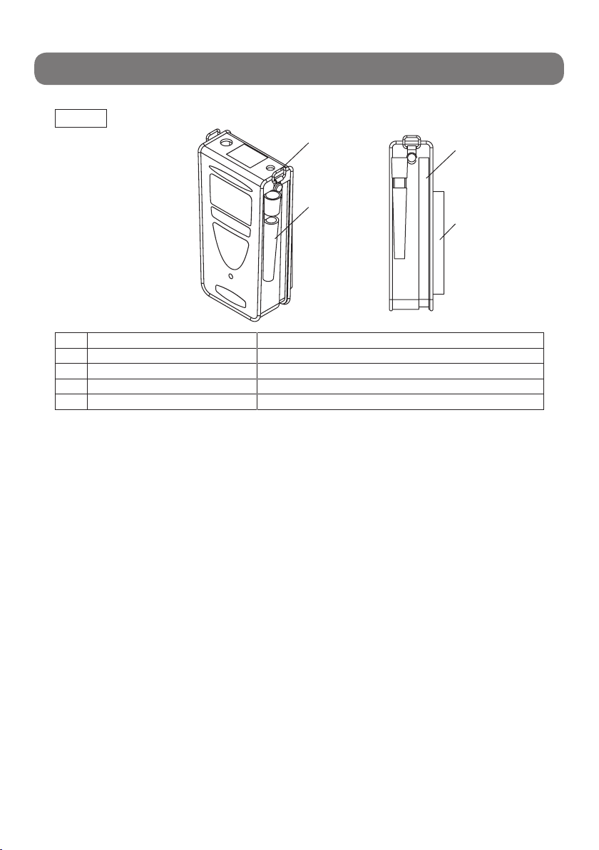
1 Shoulder belt mounting bracket Connects to the provided shoulder belt.
2 Sampling pipe holder Holds the suction attachment pipe.(XP-3180)
3 Fastener Used to extract the Gas Detector or replace the battery.
4 Back pocket Used to hold the sampling hose or provided filter.
Soft case
(1)
(2)
(3)
(4)
−8−
Operating Procedure
3. Operating Procedure
■Procedure
1. Inserting Batteries
The Gas Detector is delivered without batteries inserted. Refer to pages 19 to insert the provided
batteries.
2. Turning Gas Detector ON →Warming Up →Displaying Gas Concentration
Screen
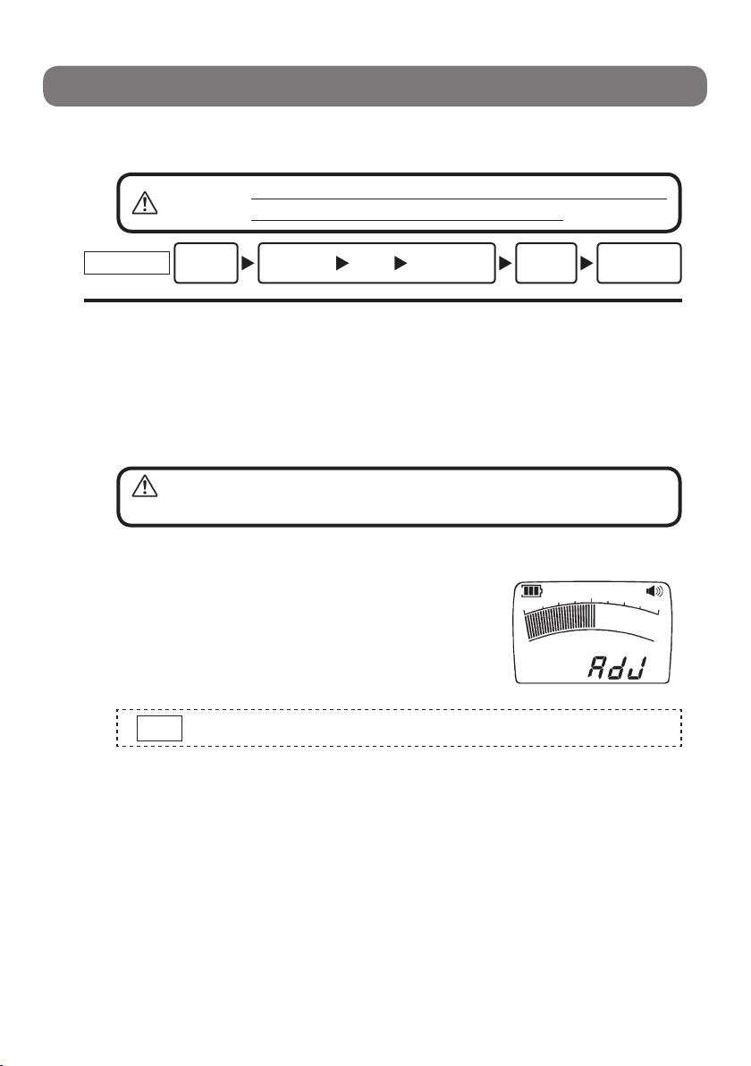
(1) Press the POWER switch. The buzzer will beep and the Gas Detector will be turned ON.
(2) The LCD main screen will display Adj and the bar graph will
count down while the Gas Detector is warming up. The LCD
sub screen will display a clock.
(3) When the sensor is stabilized, the buzzer will beep and the gas
concentration screen will be displayed.
WARNING Be sure to place the connected gas sampling hose in clean air when
turning ON the Gas Detector.
WARNING Be sure to conduct a daily inspection before
performing detection work (see page 22).
Note If an error message is displayed, refer to Error Messages on page 17.
Procedure 1Insert
the
batteries. 2Turn ON
t h e G a s
Detector.
Displays the gas
concentration
screen.
Warms
up. 3Detects 4Turn OFF the
Gas Detector
Questo manuale è adatto per i seguenti modelli
1
Indice
Altri manuali Cosmos Strumento di misura


