Crompton Tyco Electronics SWITCHBOARD INTEGRA 1540 Manuale utente

Installation and Operating Instructions
SWITCHBOARD INTEGRA 1540
http://energy.tycoelectronics.com
Energy Division
Tyco Electronics UK Limited
Crompton Instruments
Freebournes Road, Witham, Essex, CM8 3AH, UK
Tel: +44 1376 509 509
Fax: +44 1376 509 511

Crompton Switchboard
INTEGRA 1540
Power Measurements and Display Made Easy
Installation & Operating Instructions
Models INT - 1543 and INT - 1544
Crompton Instruments
Freebournes Road
Witham
Essex
CM8 3AH
England
Tel: +44 (0) 1376 509 509
Fax: +44 (0) 1376 509 511
E-Mail: [email protected]
Crompton Instruments 1540 MANUAL Issue 1 11/2002

Contents Page
Introduction 1
2 Installation 2
2.1 Display 2
2.2 EMC Installation Requirements 2
2.3 Case Dimension and Panel Cut-Out 3
2.3.1 Model INT-1540 3
2.4 Wiring 4
2.5 Auxiliary Supply 4
2.6 Fusing 4
2.7 Earth/Ground Connections 4
3 Connection Diagrams 5
3.1 View of Terminals 5
USA Style 5
3.3 European Style 6
4 Integra 1540 Display Screens 7
4.1 Screen 1 – System Screen INT-1540 7
4.2 Screen 2 – System %THD Screen 7
4.3 Screen 3 – Line to Neutral Voltages 7
4.4 Screen 4 – Line to Neutral Voltage %THD 8
4.5 Screen 5 – Line to Line Voltages 8
4.6 Screen 6 – Line to Line Voltages %THD 8
4.7 Screen 7 – Line Currents 9
4.8 Screen 8 – Line Currents %THD 9
4.9 Screen 9 – Neutral Current, Frequency and Power Factor 9
4.10 Screen 10 – Power 10
4.11 Screen 11– Active Energy (kW.h) 10
4.12 Screen 12 – Reactive Energy (kVAr.h) 10
4.13 Screen 13 – Active Power and Current Demands 11
4.14 Screen 14 – Active Power and Current Maximum Demands 11
4.15 Over Range 11
4.16 kW.h and kVAr.h Display Range 12
4.17 Error Messages 12
5 Programming 13
5.1 Password Protection 13
5.2 Set-Up Screens 16
5.2.1 Full Scale Current 16
5.2.2 Potential Transformer Ratio Primary Value 17
5.2.3 Demand Integration Time Edit 19
5.2.4 Resets 20
5.2.5 Pulsed Output, Pulse Duration 22
5.2.6 Pulse Rate 22
5.2.7 RS 485 Baud Rate 23
5.2.8 RS 485 Parity Selection 24
5.2.9 RS 485 Modbus Address 24
6 Outputs 26
6.1 Modbus‚ Implementation 26
6.2 RS485 Implementation for Johnson Controls Metasys 31
6.3 Pulsed Output 33
7 Maximum Demand Calculation 34
8 THD Calculation 35
9 Specification 36
1 Introduction
The Crompton Switchboard 1540 is a panel mounted self contained measuring, display and
communication device.
This system will measure display and communicate up to 31 electrical parameters, integrating
high accuracy measurement technology with the simplicity and visibility of 7 segment LED
displays.
All voltage and current measurements are True RMS for accurate
measurement of distorted waveforms over a wide measuring
range. The Integra 1540 has excellent harmonic handling for true
power measurement.
Available in the following configurations:
3 Phase 3 Wire Unbalanced
3 Phase 4 Wire Unbalanced
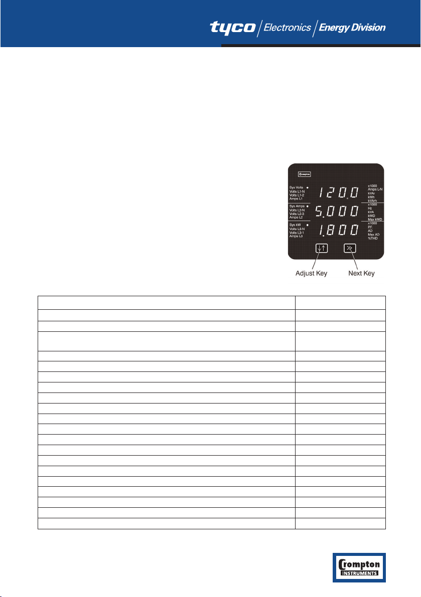
The Integra 1540 front panel has two push buttons, referred to as
“keys”. The two keys take the user through the menu structure
with ease and simplicity, to display and configure to their
individual requirements.
The parameters available are shown in the table below.
1
Integra 1540 Measured Quantity Units of measurement
System Voltage Volts
System Current (Average) Amps
Average % Total Harmonic Distortion (THD) of System Voltage % of Total RMS
and Current
Voltage L-N (4 wire only) Volts
% Total Harmonic Distortion (THD) of voltage % of Total RMS
Voltage L-L (calculated in 4 wire) Volts
Current in 3 Phases Amps
% Total Harmonic Distortion (THD) of Current % of Total RMS
Neutral Current (4 wire only) Amps
Frequency Hz
Power Factor
Active Power kW, see note 1
Reactive Power kVAr, see note 1
Apparent Power kVA
Active Energy kW.h
Reactive Energy kVAr.h
Total System Current Demand Admd
Total System Active Power Demand kWdmd
Maximum Total System Current Demand Admd
Maximum Total System Active Power Demand kWdmd
Note 1. All power related measurements are importing only unless connected as exporting unit.

A pulsed relay output, representing kW.h, with selectable pulse width, and an RS485 ModbusTM
output (see Section 4 Integra 1540 Display Screens) are available as optional features.
Connections for both are via screw clamp terminals.
2 Installation
2.1 Display
The Switchboard Integra 1540 may be mounted in a panel of any thickness up to a maximum of
0.47”. Mounting is by four 1/4- 28 UNF corner studs and nuts. Consideration should be given to
the space required behind the instrument to allow for bends in the connection cables.
As the front of the enclosure conforms to IP54 it is protected from water spray from all
directions, additional protection to the panel may be obtained by the use of an optional panel
gasket. The terminals at the rear of the product should be protected from liquids.
Switchboard Integra 1540 should be mounted in a reasonably stable ambient temperature within
the range -20 to +70°C. Vibration should be kept to a minimum and the product should not be
mounted where it will be subjected to excessive direct sunlight.
WARNINGS:
●In the interest of safety and functionality these products must be installed by a qualified
engineer, abiding by any local regulations.
●Voltages dangerous to human life are present at some of the terminal connections of these
units. Ensure that all supplies are de-energised before attempting any connection or
disconnection. External installations must be sufficient to protect human life and
equipment under fault conditions.
●These products do not have internal fuses therefore external fuses must be used for
protection for safety under fault conditions.
2.2 EMC Installation Requirements
These products have been designed to meet the certification of the EU directives when installed
to a good code of practice for EMC in industrial environments, e.g.
●Screened output and low signal input leads. Other connecting leads must be screened or
have provision for fitting RF suppression components, such as ferrite absorbers, line filters
etc., if RF fields cause problems. N.B. It is good practice to install sensitive electronic
instruments, that are performing critical functions, in EMC enclosures that protect against
electrical interference causing a disturbance in function.
●Avoid routing leads alongside cables and products that are, or could be, a source of
interference.
●To protect the product against permanent damage, surge transients must be limited to 2kV
peak. It is good EMC practice to suppress differential surges to 2kV at the source. The unit
has been designed to automatically recover in the event of a high level of transients. In
extreme circumstances it may be necessary to temporarily disconnect the auxiliary supply
for a period of greater than 5 seconds to restore correct operation.
●The current inputs of these products are designed for connection into systems via current
transformers only; where one side is grounded.
2
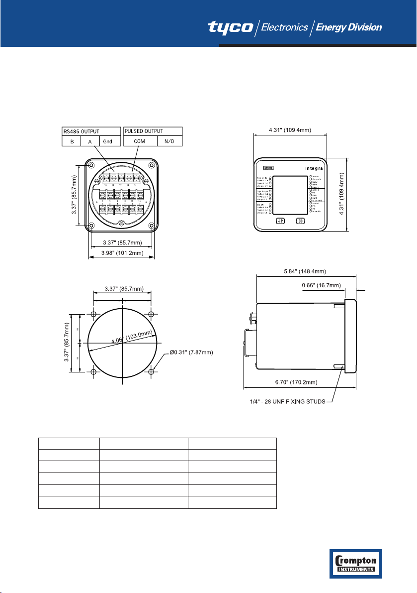
2.3 Case Dimension and Panel Cut-Out
2.3.1 Model INT-1540
3
Model JIS ANSI
DIM A 3.54” (90.0mm) 3.37” (85.7mm)
DIM B 3.90” (99.0mm) 3.98” (101.2mm)
DIM X 3.54” (90.0mm) 3.37” (85.7mm)
DIM Y 3.98” (101.2mm) 4.06” (103.0mm)
DIM Z Ø0.22” (5.5mm) Ø0.31” (7.87mm)

2.4 Wiring
Input connections are made to screw clamp terminals. Choice of cable should meet local
regulations. Terminals for both current and voltage inputs will accept up to 3mm2x 2 diameter
cables or ring lugs suitable for 6-32 screws.
Output connections are made directly to the screw clamp style terminals. The choice of cable
should satisfy local regulations. See Section 6 Outputs for more detail.
2.5 Auxiliary Supply
Switchboard Integra 1540 should ideally be powered from a dedicated supply, however it may
be powered from the signal source, providing the source remains within the limits of the chosen
auxiliary voltage.
2.6 Fusing
It is recommended that all voltage lines are fitted with 1 amp HRC fuses.
2.7 Earth/Ground Connections
For safety reasons, CT secondary connections should be grounded in accordance with local
regulations.
4
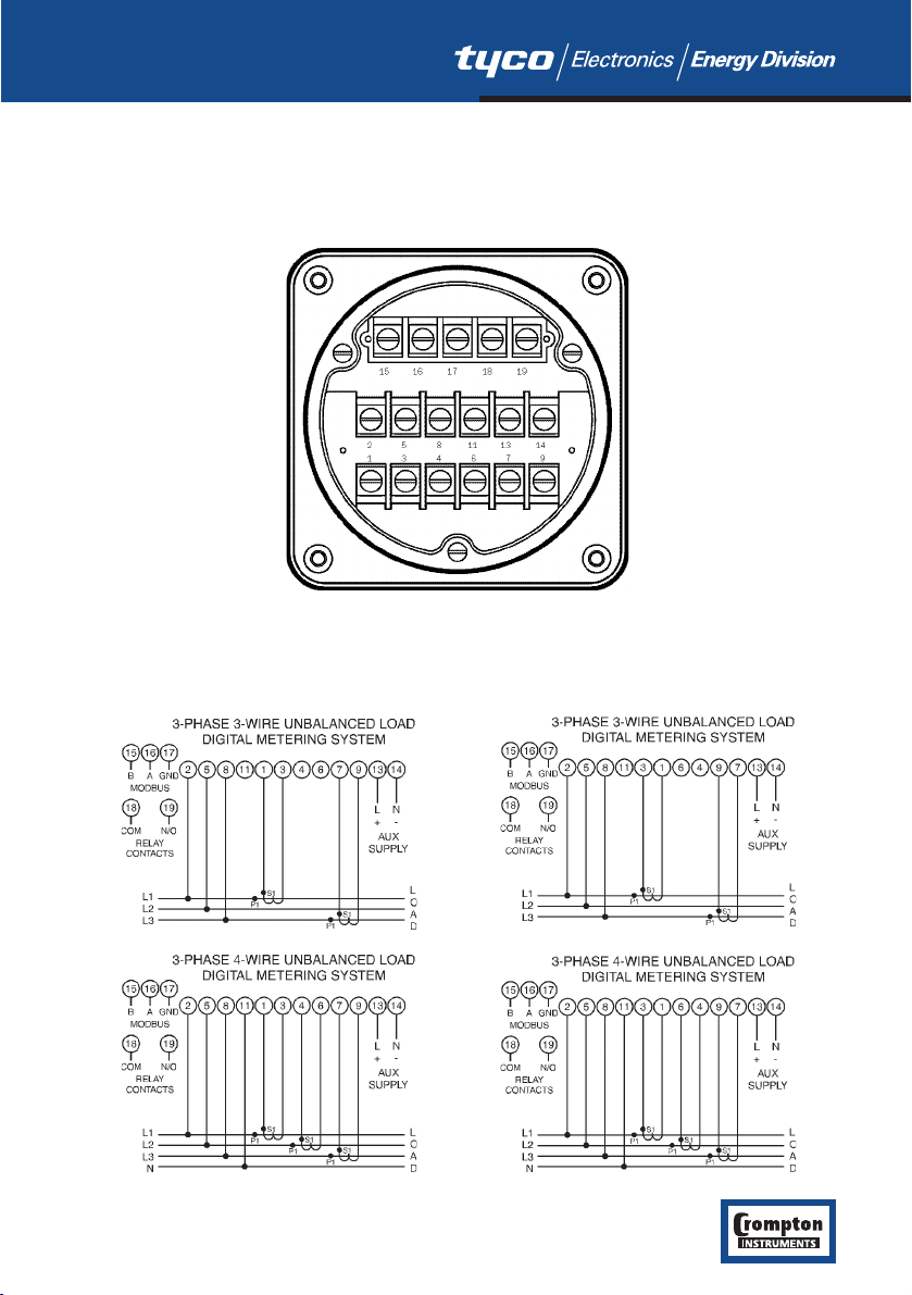
3 Connection Diagrams
3.1 View of Terminals
3.2 USA Style
Importing Connections Exporting Connections
5
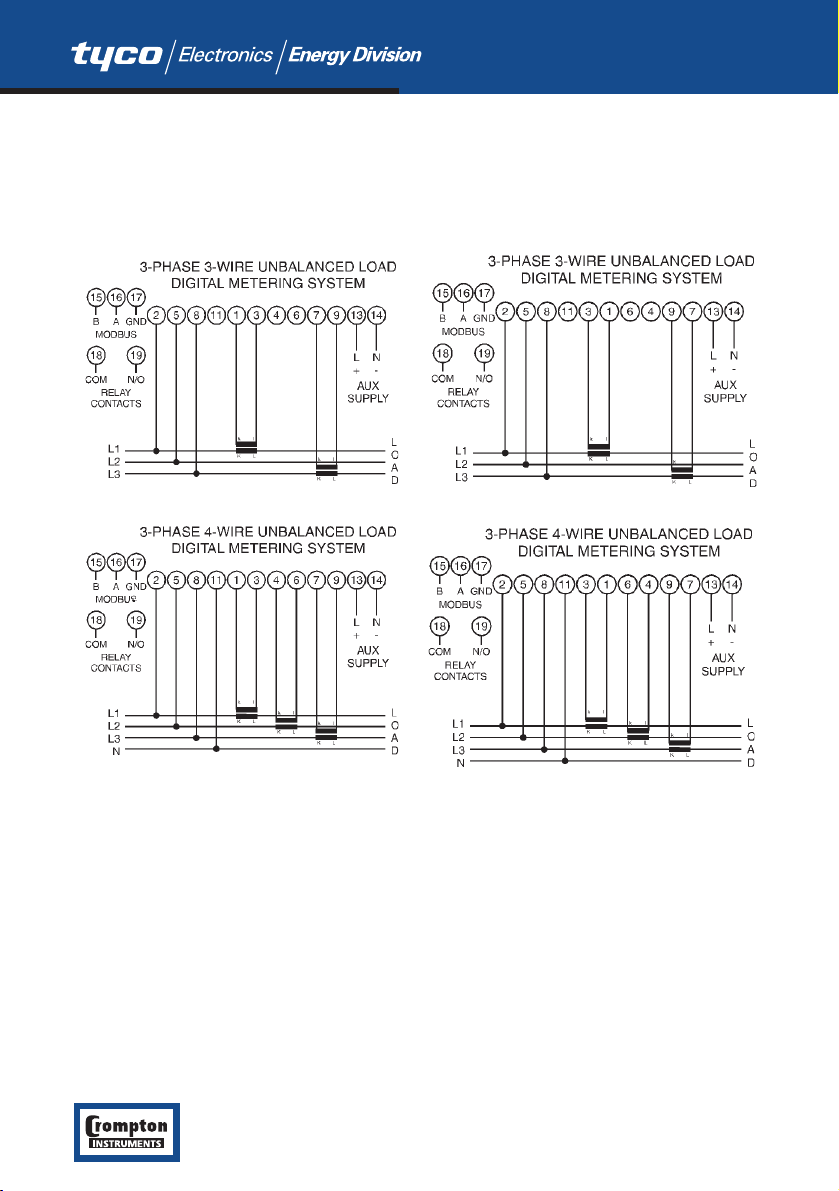
3.3 European Style
IMPORTING CONNECTIONS EXPORTING CONNECTIONS
6
4 Integra 1540 Display Screens
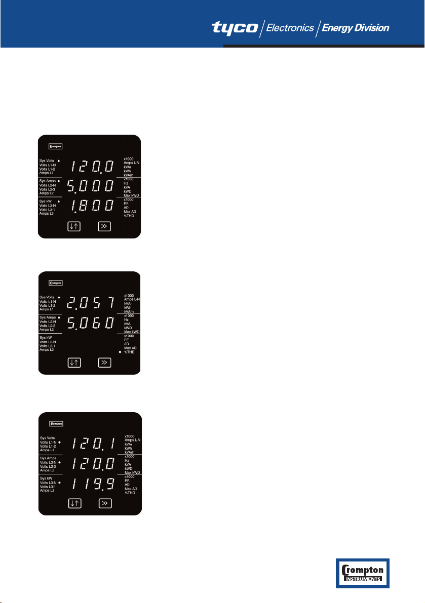
4.1 Screen 1 – System Screen INT-1540
The system screen is the default display. It appears when the unit is energised.
System Average Voltage (Volts) {Line to Line for 3 wire
systems, Line to Neutral for 4 wire systems}.
System Average Line Current (Amps).
System Total Active Power (kW).
Key >> brings up Screen 2, System %THD.
4.2 Screen 2 – System %THD Screen
Average % Total Harmonic Distortion for System Voltages.
Average % Total Harmonic Distortion for System Currents.
3 phase 3 wire supply: Key >> brings up Screen 5, L-L
Voltages.
3 phase 4 wire supply: Key >> brings up Screen 3, L-N
Voltages.
4.3 Screen 3 – Line to Neutral Voltages
Three phase, four wire systems only.
Voltage Line 1 to Neutral (Volts).
Voltage Line 2 to Neutral (Volts).
Voltage Line 3 to Neutral (Volts).
Key >> brings up Screen 4, Line to Neutral Voltage %THD.
7
Indice
Altri manuali Crompton Strumento di misura


