Danaher Precision Systems DPS BDM-6 Manuale utente

DPS BDM-6™ High
Performance Brush &
Brushless Servo
Motor Amplifier
DPS Controllers

Before using any DPS product, please read all materials
shipped with your system. It is sugested that you keep these
materials near the system for troubleshooting and maintenance
assistance.
Always turn off power before connecting or disconnecting
cables or working near system.
This system is to be used only in accordance with the enclosed-
specifications.
Specifications and configurations are subject to change without
notice.
Thank you for selecting Danaher Precision Systems as your
positioning equipment supplier. We understand that you can
choose from a number of competitive suppliers, and are
pleased that you have selected DPS.
This manual addresses the DPS BDM-6™ Servo Amplifier.
As you unpack and begin to use our product, we would
like your conclusions as to our products’ appearance,
quality, precision, and suitability to your ultimate
application. By providing us with feedback in these and
other areas, you can become an active participant in our
on-going program of continuous improvement.
Our Customer Service department can be reached at:
We encourage you to visit our web site at www.NEAT.com.
It includes information on new products, along with our
existing product catalog, a Motion Control Handbook
covering 33 technical topics, and other useful information.
Thank you again for choosing Danaher Precision Systems.
We look forward to serving you in the future.
Overview
DPS BDM-6™ Servo Amplifier Manual
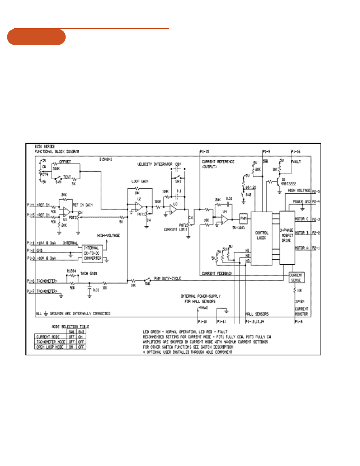
Features, Product Description, Schematic. . . . . . . . . . . . . . . . . . . . . . . . . 2
Specifications . . . . . . . . . . . . . . . . . . . . . . . . . . . . . . . . . . . . . . . . . . . . . . . 3
Pin Functions. . . . . . . . . . . . . . . . . . . . . . . . . . . . . . . . . . . . . . . . . . . . . . . . 4
Potentiometer & Switch Functions. . . . . . . . . . . . . . . . . . . . . . . . . . . . . . . 5
Commutation Sequence, Operating Mode Selection, Set Up . . . . . . . . . 6
Current Limit Adjustments, Power Supplies . . . . . . . . . . . . . . . . . . . . . . . 7
Typical System Wiring, Mounting Dimensions, Tolerances. . . . . . . . . . . . 8
Warranty & Terms. . . . . . . . . . . . . . . . . . . . . . . . . . . . . . . . . . . . . . . . . . . 10
Contents
phone: 603.893.0588 (1.800.227.1066 in the US)
fax: 603.893.8711
e-mail: suppo t@NEAT.com
Dahaner Precision Systems
7C Raymond Avenue
Salem, NH 03079
Warnings &
Safety
Information
Features &
Description
Features
• Surface-mount technology
• Small size, low cost, easy to use
• DIP-switch selectable: Current, velocity, or open
loop mode
• Four quadrant rgenerative operation
Description
The BDM-6 PWM Servo Amplifier is designed to drive
brush/brushless DC motors at a high switching frequency. A
single red/green LED indicated operating status. The BDM-6
amplifier is fully protected against over-voltage, over-current,
over-heating, and short-circuits. It interfaces with digital con-
trollers or can be used as a stand-alone drive. This model ony
requires a single, unregulated DC power supply. Loop gain,
current limit, input gain, and offset can be adjusted using 15-
turn potentiometers. the offset-adjusting potentiometer can
also be used as an on-board input signal for testing purpose,
when SW-4 (DIP switch) is on.
DPS BDM-6™ Servo Amplifier Manual

Specifications
Models
Power Stage Specifications A6 A8
DC Supply Voltage 20–60V 20–80V
Peak Current (2 second maximum) ±12A ±15A
Maximum Continuous Current ±6A ±7.5A
Minimum Load Inductance 200mH 200mH
Switching Frequency 33kHz ±15%
Heatsink (Base) Temperature Range 0° to +65°C; disables if > 65°C
Power Dissipation at Continuous Current 18W 30W
Over Voltage Shutdown (Self Reset) 62V 86V
Bandwidth (Load Dependent) 2.5kHz 2.5kHz
Mechanical Specifications
Power Connector Screw Terminals
Signal Connector Molex Connector
Size 5.09 x 2.98 x 0.99 inches
129.3 x 75.8 x 25.1 mm
Weight 10 oz.
0.28 kg

Pin Functions
Connector Pin Name Description / Notes I/O
P1 1 +10V @ 3mA OUT For customer use O
2 SIGNAL GND Reference Ground GND
3 -10V @3mA OUT For customer use O
4 +REF IN Differential reference input, maximum ±15V, I
40k input resistance
5 - REF IN See pin 4 I
6 -TACH IN Tachometer input, maximum ±60 VDC, 60k input I
resistance
7 +TACH / GND Ground GND
8 CURRENT MONITOR OUT Current monitor. 1V = 2A O
9 INHIBIT IN This TTL level input signal turns off all power I
devices of the ‘H’ bridge when pulled to the
ground. This inhibit will cause a fault condition
and a red LED.
10 +V HALL OUT Power for HALL sensors short circuit protected, O
+6V @ +30mA.
11 GND See pin 10 GND
12 HALL 1 HALL sensor inputs, TTL logic levels, internal 5 I
K MISSING SYMBOL pull-up. Maximum low level input is 1.5V,
minimum high level input is 3.5V.
13 HALL 2 See pin 12.
14 HALL 3 See pin 12.
15 CURRENT REFERENCE Monitors the input signal connected directly O
OUT to the internal current amplifier. 7.25V = maximum
current. See current limit adjustment information
below.
16 FAULT OUT TTL level output. Becomes high during output O
(red LED) short circuit, over voltage, inhibit, over
temperature and during power on reset. Fault
condition indicated by red LED.
P2 1 MOTOR A Motor phase A connection O
2 MOTOR B Motor phase B connection O
3 MOTOR C Motor phase C connection O
4 POWER GND Power ground GND
5 HIGH VOLTAGE DC power input I

Potentiometer
Switch
Functions
Potentiometer Description Turning CW
Pot 1 Loop gain adjustment in open loop and velocity modes. Increases loop gain
Turn this pot fully CCW in current mode.
Pot 2 Current limit. It adjusts both continuous and peak current Increases current limit
limit while maintaining their ratio (50%).
Pot 3 Reference gain. it adjusts the ratio between input signal Increases reference
and output variables (voltage, current, velocity). input gain
Pot 4 Test / Offset. Used to adjust any imbalance in the input NA
signal or in the amplifier. when SW4 (DIP switch) is ON,
the sensitivity of this pot is greatly increased, thus it can be
used as an on-board signal source for testing purposes.
Switch Function Description Setting
On Off
1 Duty-cycle feedback. Open Loop No Effect
2 60 / 120° commutation phasing setting. 120° 60°
3 Loop integrator. This capacitor normally ensures Shorts out the Velocity/voltage
“error-free” operation in velocity mode by velocity/voltage loop integrator
reducing the error-signal (output of loop integrator capacitor
summing amplifier) to zero. capacitor. operating.
4 Test / Offset. Sensitivity of the “offset” pot. Test Offset
Used as an on-board reference signal in test mode.

Operating Mode Selection
• Current Mode
• Open Loop Mode
• Tachometer Mode
These modes can be selected by the DIP switches according to
the chart in the block diagram.
Set-Up
• Set amplifier in open loop mode, switch TEST-OFFSET
switch on.
• Set current limit according to maximum motor current.
• Check poswer and connect it to amplifier.
• Connect HALL sensor inputs. LED should be green. Hand
turn motor shaft one revolution. LED should remain green.
If not, change 60/120° phasing switch.
• Connect the three motor wires. There are six ways to
connect the three wires to the MOTOR-A, MOTOR-B,
MOTOR-C pins. Try all six combinations and choose the
best one. If the motor runs slower in one direction, or you
have to move the shaft to start the motor, the combination
is incorrect.
• Adjust TEST-POT for zero speed and switch TEST switch
OFF.
• Set mode suitable for your application.
Operating
Mode Selection
commutation
Sequence
Key
1: High TTL level HALL sensor input (+5V)
0: Low TTL level HALL sensor input (0V)
H: Motor output is high or switching
L: Motor output is low
X: Motor output is off (floating)
The last two lines are the invalid commutation states. In these
states, LED red color indicates that the drive is disabled.
To change direction, swap HALL-1 and HALL-3, then MOTOR-A
and MOTOR-B.
60° 120° Motor
HALL 1 HALL 2 HALL 3 HALL 1 HALL 2 HALL 3 A B C
100100HXL
110110KHL
111010LHX
011011LXH
001001KLH
000101HLX
101111XXX
010000XXX

Current Limit
Adjustments
Current Limit Adjustments
The amplifier features separate peak and continuous current
limit adjustments, but the ratio between them is fixed (50%).
The current limit adjustment potentiometer POT2 adjusts both
peak and continuous current limit at the same time, it has ten
turns and is linear. Thus, to adjust the current limit, turn the
“pot” counterclockwise to zero, then turn clockwise to the
appropriate value.
P1-15 is the input to the internal current amplifier stage to the
motor. Since the output current is proportional to P1-15, the
adjusted current limit can easily be observed at this pin without
connecting the motor.
The actual current can be monitored at pin P1-8.
Recommended
Power Supplies
Recommended Power Supplies
For single axis applications: PS300W
For multi-axis applications: PS2X300W

Typical
System Wiring
Mounting
Dimensions
Tolerances:
.xx - ±0.01
.xxx - ±0.005
Scale: 1:1

Indice


