Deif AGC 150 Manuale utente

OPERATOR'S MANUAL
AGC 150
Stand-alone
4189341311A

1. Introduction
1.1 Symbols for hazard statements......................................................................................................................................................................................... 3
1.2 About the operator's manual...............................................................................................................................................................................................3
1.3 Warnings and safety.................................................................................................................................................................................................................4
1.4 Legal information.......................................................................................................................................................................................................................4
2. About the AGC 150 Stand-alone
2.1 Display, buttons and LEDs................................................................................................................................................................................................... 5
2.2 Display settings.......................................................................................................................................................................................................................... 6
2.3 Mimic function............................................................................................................................................................................................................................. 6
2.4 Running modes...........................................................................................................................................................................................................................7
3. Menus
3.1 Menu structure............................................................................................................................................................................................................................ 9
3.2 Settings menu..............................................................................................................................................................................................................................9
3.2.1 Menu numbers..................................................................................................................................................................................................................10
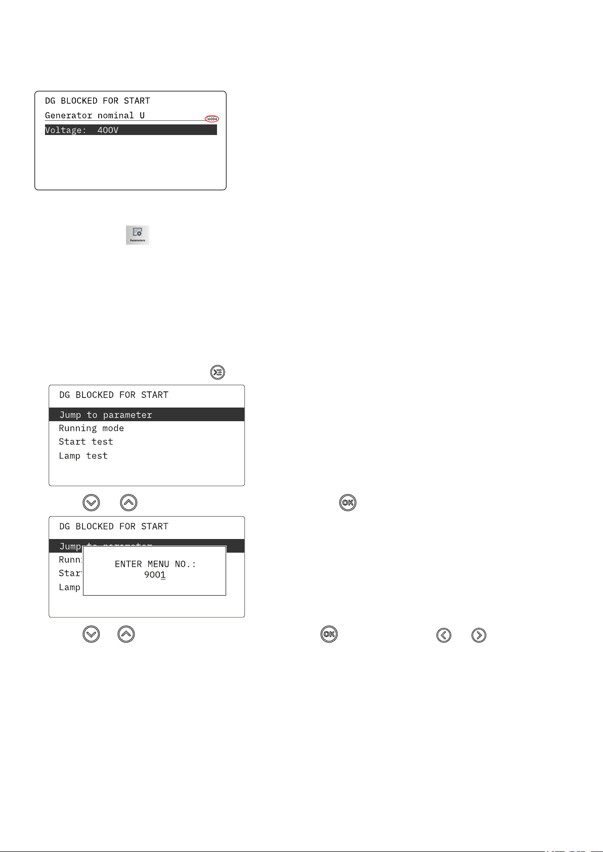
3.2.2 The jump to parameter function................................................................................................................................................................................ 10
3.3 View menu................................................................................................................................................................................................................................... 10
3.3.1 Display views..................................................................................................................................................................................................................... 11
3.3.2 Display text.........................................................................................................................................................................................................................12
3.4 Status texts.................................................................................................................................................................................................................................13
3.5 Service view............................................................................................................................................................................................................................... 14
3.6 Exhaust after-treatment (Tier 4/Stage V).................................................................................................................................................................... 14
4. Alarm handling and log list
4.1 Alarm handling......................................................................................................................................................................................................................... 17
4.2 Logs menu.................................................................................................................................................................................................................................. 18
OPERATOR'S MANUAL 4189341311A EN Page 2 of 18

1. Introduction
1.1 Symbols for hazard statements
DANGER!
This shows dangerous situations.
If the guidelines are not followed, these situations will result in death, serious personal injury, and equipment damage or
destruction.
WARNING
This shows potentially dangerous situations.
If the guidelines are not followed, these situations could result in death, serious personal injury, and equipment damage
or destruction.
CAUTION
This shows low level risk situation.
If the guidelines are not followed, these situations could result in minor or moderate injury.
NOTICE
This shows an important notice
Make sure to read this information.
1.2 About the operator's manual
This document gives the necessary information to operate the controller.
CAUTION
Installation errors
Read this document before working with the AGC 150 controller. Failure to do this may result in human injury or damage
to the equipment.
Intended users of the operator's manual
The operator's manual is for the operator that uses the controller regularly.
The manual describes the LEDs, buttons and screens on the controller, alarm handling, and the logs menu.
OPERATOR'S MANUAL 4189341311A EN Page 3 of 18

1.3 Warnings and safety
Factory settings
The controller is delivered pre-programmed from the factory with a set of default settings. These settings are based on typical values
and may not be correct for your system. You must therefore check all parameters before using the controller.
Data security
To minimise the risk of data security breaches:
• As far as possible, avoid exposing controllers and controller networks to public networks and the Internet.
• Use additional security layers like a VPN for remote access, and install firewall mechanisms.
• Restrict access to authorised persons.
1.4 Legal information
Third party equipment
DEIF takes no responsibility for the installation or operation of any third party equipment, including the genset. Contact the genset
company if you have any doubt about how to install or operate the genset.
Warranty
NOTICE
Warranty
The controller is not to be opened by unauthorised personnel. If opened anyway, the warranty will be lost.
Disclaimer
DEIF A/S reserves the right to change any of the contents of this document without prior notice.
The English version of this document always contains the most recent and up-to-date information about the product. DEIF does not
take responsibility for the accuracy of translations, and translations might not be updated at the same time as the English document.
If there is a discrepancy, the English version prevails.
Copyright
© Copyright DEIF A/S. All rights reserved.
Software version
This document is based on the AGC 150 software version 1.10.0.
OPERATOR'S MANUAL 4189341311A EN Page 4 of 18

2. About the AGC 150 Stand-alone
2.1 Display, buttons and LEDs
4
3
3
5
6
7
8
9
15 14 11 1112 12
1
17
16
2 3 3
18
1013
No. Name Function
1 Power Green: The controller power is ON.
OFF: The controller power is OFF.
2 Display screen
Resolution: 240 x 128 px.
Viewing area: 88.50 x 51.40 mm.
Six lines, each with 25 characters.
3 Navigation Move the selector up, down, left and right on the screen.
4 OK Go to the Menu system.
Confirm the selection on the screen.
5 Back Go to the previous page.
6 AUTO mode
The controller automatically starts and stops (and connects and disconnects) the genset. No operator
actions are needed. The controller also automatically opens and closes the mains breaker (open
transitions, since there is no synchronisation).
7 Silence horn Turns off an alarm horn (if configured) and enters the Alarm menu.
8 Shortcut menu Access the Jump menu, Mode selection, Test, Lamp test
9 SEMI-AUTO
mode
The controller cannot automatically start, stop, connect or disconnect the genset, or open and close
the mains breaker.
The operator or an external signal can start, stop, connect or disconnect the genset, or open or close
the mains breaker.
10 Mains symbol Green: Mains voltage and frequency are OK. The controller can close the breaker.
Red: Mains failure.
11 Close breaker Push to close the breaker.
12 Open breaker Push to open the breaker.
OPERATOR'S MANUAL 4189341311A EN Page 5 of 18

No. Name Function
13 Breaker symbols Green: Breaker is closed.
Red: Breaker failure.
14 Generator
Green: Generator voltage and frequency are OK. The controller can close the breaker.
Green flashing: The generator voltage and frequency are OK, but the V&Hz OK timer is still running.
The controller cannot close the breaker.
Red: The generator voltage is too low to measure.
15 Engine
Green: There is running feedback.
Green flashing: The engine is getting ready.
Red: The engine is not running, or there is no running feedback.
16 Stop Stops the genset if SEMI-AUTO or Manual is selected.
17 Start Starts the genset if SEMI-AUTO or Manual is selected.
18 Load symbol Green: The supply voltage and frequency are OK.
Red: Supply voltage/frequency failure.
2.2 Display settings
To adjust for ambient lighting, configure the display settings.
Settings > Basic settings > Controller settings > Display > Display control
Parameter Text Range Default
9151 Backlight dimmer 0 to 15 * 12
9152 Green LEDs dimmer 1 to 15 * 15
9153 Red LEDs dimmer 1 to 15 * 15
9154 Contrast level -20 to +20 0
9155 Sleep mode timer 1 to 1800 s 60 s
9156 Enable (Sleep mode timer) OFF
ON ON
9157 Alarm Jump OFF
ON ON
9158 Engineering units Bar/Celcius
PSI/Fahrenheit Bar/Celcius
* Note: Low numbers are minimum brightness and high numbers are maximum brightness.
2.3 Mimic function
With the mimic function you can select how the control buttons and LEDs are shown on the controller's display.
Settings > Basic settings > Controller settings > Display > LED mimic
Parameter no. Item Range
6082 LED mimic
Standard with genset
Standard
Guided with genset
Guided
OPERATOR'S MANUAL 4189341311A EN Page 6 of 18

Standard
The control buttons and LEDs are shown.
If you stop the genset, the motor/generator symbols are not shown.
Standard with genset
The control buttons and LEDs are shown.
If you the stop the genset, the motor/generator symbols are shown in
red.
Guided
Active control buttons and LEDs are shown inactive are not shown.
Example: The AGC 150 Stand-alone is in SEMI-AUTO mode, and the
genset is not operating. Only the start button is shown, as this is the
only possible action.
Guided with genset
Active control buttons, LEDs and the motor/generator symbols are
shown, inactive are not shown.
Example: The AGC 150 Stand-alone is in SEMI-AUTO mode. The
genset is not operating. The only possible action is to start the genset,
and so only the start button and the red motor/generator symbols are
shown.
All Mimic settings
Red breaker symbol:
• Breaker position failure
• Breaker close failure
2.4 Running modes
The controller has three different running modes, a block mode and a test mode. Push the Shortcut button and select Running
Modes to see the running modes and block mode. Configure the test mode in Settings > Power set points > Test. To
select the test mode push the Shortcut button and select Start Test.
Mode Description
AUTO The controller automatically starts and stops (and connects and disconnects) the genset. The operator cannot start
a sequence manually.
SEMI-AUTO
The controller cannot automatically start, stop, connect and disconnect the genset or open and close the mains
breaker. The operator can start these sequences using the buttons on the controller, Modbus commands or the
digital inputs. If the genset starts in semi-auto mode, it will operate at nominal values.
MANUAL The operator can use the digital increase/decrease inputs (if they are configured) and the Start and Stop buttons.
When the genset starts in manual mode, it will start without subsequent regulation.
OPERATOR'S MANUAL 4189341311A EN Page 7 of 18

Mode Description
BLOCK The controller cannot start a sequence, for example the start sequence. Select the block mode when you do
maintenance work on the genset.
Test The test sequence will start when you select the test mode.
NOTE The genset will shut down if you select the block mode while the engine is operating.
OPERATOR'S MANUAL 4189341311A EN Page 8 of 18

3. Menus
3.1 Menu structure
The controller has two menu systems, which can be used without password entry:
•The View menu system: Shows the operating status and values. The system has 20 configurable windows, that can be entered
with the arrow buttons.
•The Settings menu system: The operator can see the controller's parameters. A password is necessary to change the
parameter settings.
3.2 Settings menu
You can configure the controller in the settings menu and you can also find information, which is not available in the view menu.
From the view menu, push the button to find the settings menu. Use the and buttons to find the different settings
parameter and select with the button.
Settings menu example
This is an example of how to change the nominal voltage settings.
!
Push
Push
Push
Push
Push
Push
OPERATOR'S MANUAL 4189341311A EN Page 9 of 18

3.2.1 Menu numbers
Each parameter has a menu number. You can find the number in the upper right corner on the display screen.
You can also find the menu number with the utility software:
1. Select Parameters from the vertical toolbar on the left.
2. Set the view mode to list. The view mode can be found in the left corner of the screen.
3. The menu numbers are in the Channel column.
3.2.2 The jump to parameter function
If you know the menu number for a parameter, you can use the jump to parameter function to go directly to the parameter.
On the controller
1. From the view menu, push the Shortcut button to see the jump to parameter function:
2. Use the and buttons to go to Jump to parameter and push the button.
3. Use the and buttons to change the numbers, and push the button to save. Use the and buttons to move to
the next number.
3.3 View menu
The view menu is shown when the controller is turned on, and you can see the operating status and values. The event and alarms
list will also be shown if an alarm is on.
OPERATOR'S MANUAL 4189341311A EN Page 10 of 18
Altri manuali per AGC 150
9
Indice
Altri manuali Deif Strumento di misura

Deif
Deif MIB 8000 Manuale utente

Deif
Deif MIC-2 MKII Manuale utente

Deif
Deif Insight Manuale utente

Deif
Deif WSI Manuale utente

Deif
Deif BRW-2 Manuale utente

Deif
Deif XDi Series Manuale utente

Deif
Deif MIQ96-2 Manuale utente

Deif
Deif BRW-2 Manuale utente

Deif
Deif XL Manuale utente

Deif
Deif MIB 7000 Manuale utente


