
Diehl Metering SHARKY 774 COMPACT Manuale utente
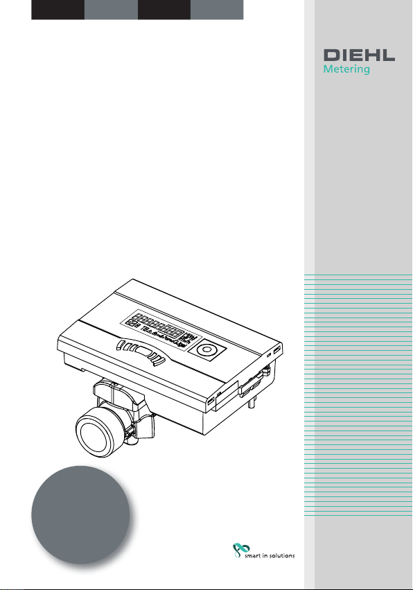
Ultrasonic energy meter
Contatore di energia ad
ultra suoni
Ultralydsenergimålere
Ultraljuds-energimätare
Installation guide
Istruzioni per il montaggio
Installationsvejledning
Monteringsanvisning
English Italiano Dansk Svenska
This guide must
be given to the end
consumer. Consegnare
queste istruzioni al cliente
nale. Denne vejledning
skal aeveres til montøren.
Denna bruksanvisning
ska överlämnas till
kunden.
-2-
English Italiano Dansk Svenska
II
I
2
1
4
3
5
A
B
A
B
A
B

-3-
English Italiano Dansk Svenska
Table of content
1. General...............................................................................4
2. Transport and storage........................................................5
3. Installationofenergymeter(g.I)...................................5
4. Temperature sensor...........................................................7
4.1 Installation in the ball valve with adapter................................... 8
4.2 Installation in a pocket.............................................................8
5. Start-up operation..............................................................9
5.1 Inlet / outlet setting (optional ex works).................................... 9
6. Communication ................................................................11
6.1 Communication via radio........................................................ 11
6.2 M-Bus Communication module................................................ 11
7. Display..............................................................................12
8. Operation .........................................................................13
9. Display Error codes ..........................................................14
10. Disposal............................................................................14
11. Declaration of conformity for MID meters.......................14
11.1 EU DoC 774/1........................................................................ 51
11.2 EU DoC 774 noMID/0............................................................. 53
-4-
English Italiano Dansk Svenska
1. General
This guide is intended for trained specialised personnel. Therefore, it does
not include basic working steps.
The seal on the energy meter must not be damaged!
A damaged seal will result in immediate invalidation of the factory
warranty and verication. The cables supplied with the meter
must neither be shortened, extended nor changed in any other way.
Legal regulations and operating instructions for the use of energy
meters must be observed!
The installation must only be carried out by a specialist energy
meter installation and electrical company. The personnel must
be trained in the installation and handling of energy meters and electrical
devices as well as the applicable guidelines.
Medium: Water, according to CEN/TR 16911.
If water additives are used (e.g. corrosion protection), the user must
make sure that the corrosion resistance is adequate.
This product is designated (where relevant) as a pressure main-
taining component in the sense of the Pressure Equipment Direc-
tive (PED) and may only be operated as a pressure maintaining
component with temperature sensors suitable for this purpose.
This product is not intended for used as a safety device in the sense of the
Pressure Equipment Directive (PED).
The medium temperature is specied as 5 ... 105 °C (130 °C)
The temperature range depends on variant and nominal size.
The exact temperature range is shown on the type plate.
The encapsulated variant is to be used if condensation is expected.
The operating/ambient conditions are 5 … 55 °C; IP 54/64; 93 % rel.
humidity.
Ambient temperatures below 35 °C have a positive eect on battery
lifetime.
If the ow sensor is insulated with the pipeline, the calculator
must be accessible.
-5-
English Italiano Dansk Svenska
Detailed user guide available at https://www.diehl.com/metering/en/
support-center/download-center/.
The Software IZAR@Mobile2 is used for reading out data and conguration
and can be downloaded from the Internet under:
https://www.diehl.com/metering/en/support-center/download-center/
Changing of communication relevant parameters can result in
the loss of OMS certication.
2. Transport and storage
Unpacking
Energy meters are measuring devices and must be handled with care. To
protect against damage and soiling, they should only be unpacked imme-
diately prior to installation.
Transport
The transport of the meter is permitted only in the original package.
When sending wireless measuring instruments / components by
air, disable the wireless (place in aircraft mode) before shipping.
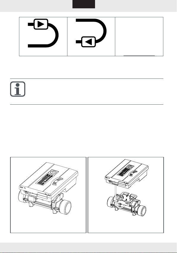
3. Installationofenergymeter(g.I)
Depending on the design and application (heat or cooling meter), the
energy meter is installed in either the hot or cold line of the system.
The ow sensor must be installed so that the ow direction matches
the arrow direction on the sensor.
Depending on the version, the ow sensor must be installed in inlet or
outlet. The installation position is displayed in the info loop 3.4 (see
"Information loop (3)" on page 13) and, if necessary, also by means
of a pictogram.
-6-
English Italiano Dansk Svenska
no pictogram
(Installation position
can be set on site,
5.1 on page 9)Inlet Outlet
Calming sections are not necessary before and after the ow sensor.
For systems without temperature mixing, a straight calming section of
3-10 x DN upstream of the ow sensor is recommended.
The meter can be installed in both horizontal and vertical pipe
sections, provided air bubbles cannot collect in the meter.
The ow sensor must always be lled with liquid.
Avoid frost at the meter.
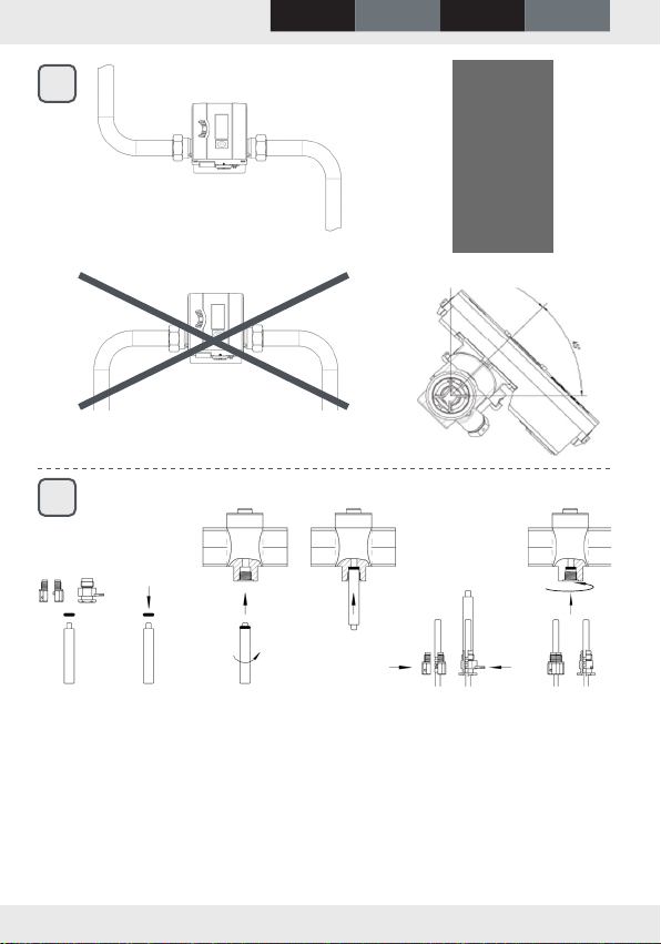
We recommend installing the ow sensor tilted through 45°.
The minimum system pressure must be 1 bar to avoid cavitation.
Make sure the meter is installed suciently far away from possible
sources of electromagnetic interference (switches, electric motors,
uorescent lamps etc.).
If possible install the cables of the ow sensor or temperature sensor
freely suspended (not bundled - aerial eect) with sucient distance
from electromagnetic interference sources.
T: 5 … 90 °C
Twater> Tambient
T: 5 … 105 / 130 °C
Twater< Tambient
-7-
English Italiano Dansk Svenska
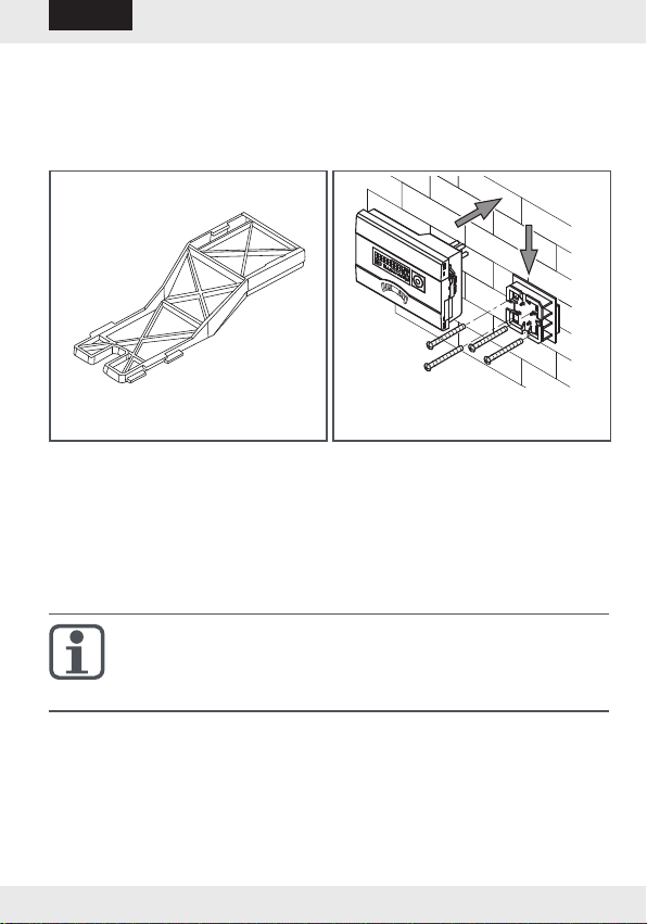
For medium temperatures from 90°C or for TWater<TAmbient (cooling
meter application or heat meter with cooling tari application) the cal-
culator must be removed and tted at a sucient distance from any
heat sources. A wall holder (optional) or a spacer holder (optional) is
available for this purpose.
Spacer holder Wall mounting
It is recommended that shut-o valves are tted before and after the
energy meter to simplify removing the meter.
The meter should be installed in a conveniently accessible position for
service and operating personnel.
Initial operation is to be carried out and recorded after installation.
4. Temperature sensor
Handle the temperature sensor carefully!
The sensor cables are provided with coloured type plates:
Red: Sensor in the hot line
Blue: Sensor in the cold line
The connecting cables must not be shortened or extended.
The free temperature sensors can be tted so they are directly sub-
merged (e.g. ball valve) or in a pocket tested for conformity for this
sensor type.
Sensors must be installed symmetrically.

-8-
English Italiano Dansk Svenska
4.1 Installation in the ball valve with adapter
(coupling set in a separate bag)
Use ball valves with installation option for temperature sensor with thread
M10 x 1.
Preparatory measures
Close the ball valve.
Unscrew the plug screw from the ball valve.
Installation(seeg.II)
1. Place the O-ring from the attached coupling set (type A or B) on the
mounting pin.
2. Insert the O-ring with the mounting pin into the sensor hole of the ball
valve (turn the mounting pin).
3. Position the O-ring in its nal position using the other end of the
mounting pin.
4. Fastening screws
Type A (plastic) - plug the fastening screw onto the temperature sen-
sor.
Type B (brass) - insert the temperature sensor in the fastening screw
and place the sensor in the mounting pin. Press in the dowel pin com-
pletely and remove the mounting pin.
5. Insert the temperature sensor with the securing tting in the ball
valve and manually tighten (2-3 Nm).
4.2 Installation in a pocket
It is recommended that temperature sensors for DN25 rated sizes or
smaller are only tted in new installations such that they are directly
immersed.
This ensures higher measuring accuracy.
-9-
English Italiano Dansk Svenska
5. Start-up operation
Once the meter has been installed, the components (calculator, volume
measuring component and both temperature sensors) must be sealed
with a tamper-proof seal and the meter started up by a specialist com-
pany approved according to the legislation.
Check the display for a plausible indication of ow rate and temper-
atures.
User guide for further Information is available at
https://www.diehl.com/metering/en/support-center/download-center/
5.1 Inlet/outletsetting(optionalexworks)
Optionally, the installation position of the meter can be set in-situ in loop 3
("3.4" on page 13). Consequently installation in the inlet (ow) or outlet
(return) is possible.
This setting must be made prior to initial operation of the meter.
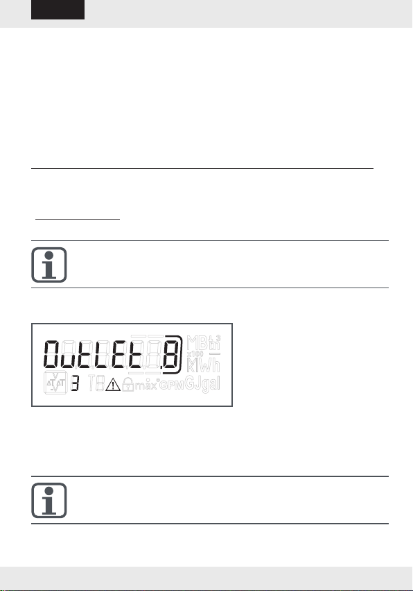
As supplied, the outlet (return) is pre-set and is shown as follows in the
display. Setting and number of possi-
ble changes.
To changeover, switch to the "Outlet" window in loop 3 (see 9. Operation).
Pressing and holding the button for > 6 s changes the display/setting to
"Inlet".
This setting can be changed a total of 8 times by pressing the button.
The display changes during the 6 s.
This does not inuence functioning.
-10-
English Italiano Dansk Svenska
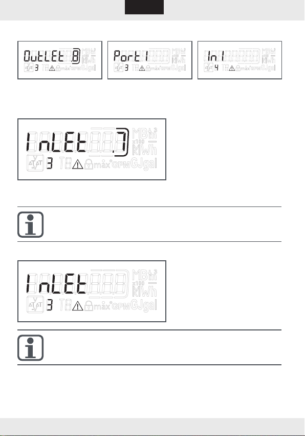
Sequence during changing
Button pressed <3s Button pressed >3s
If the button is pressed and then held for > 6 s, the meter performs the
command shown in the display. In each change, the framed
number in the display is
reduced by 1.
After 8 changes, it is no longer possible to change the installation position.
The possibility of changing lapses either immediately upon
detection of water, or after three hours’ operation without error
detection (pre-set ex works).
The following indication appears in the display (example):
The changes indication dis-
appears.
When changing the installation position, the sensors must be
matched to the actual installation (see chapter 4).
Indice
Lingue:
Altri manuali Diehl Metering Strumento di misura

Diehl Metering
Diehl Metering IZAR DOSING Manuale operativo

Diehl Metering
Diehl Metering IZAR PULSE H Manuale utente

Diehl Metering
Diehl Metering HYDRUS 171A Manuale utente

Diehl Metering
Diehl Metering Hydrus DN 15 Series Manuale utente

Diehl Metering
Diehl Metering IZAR RADIO EXTERN AIR Manuale utente

Diehl Metering
Diehl Metering HYDRUS 171A Manuale utente

Diehl Metering
Diehl Metering Sharky 775 Istruzioni per l'installazione

Diehl Metering
Diehl Metering Sharky 775 Manuale utente

Diehl Metering
Diehl Metering Sharky 775 Manuale utente

Diehl Metering
Diehl Metering HYDRUS 171A Manuale utente


