Dormakaba MotionIQ ED-CAN Manuale utente

DE
ED-CAN
060634 45532/16923 - 2023-04 1/8
Informationen zu diesem Dokument
Inhalt und Zweck
Der Inhalt dieser Kurzanleitung ist ein Auszug aus der vollständigen
Anleitung und beschränkt sich auf wichtige Informationen zum Pro-
dukt und dessen Inbetriebnahme. Die vollständige Anleitung ist
über den QR-Code abrufbar.
Zielgruppe
Das Produkt darf nur von einer Elektrofachkraft montiert und in Be-
trieb genommen werden.
Sicherheit
WARNUNG
Gefahr durch Ausfall von Schutz- und Sicherheitseinrichtungen
Die Leitungsverlegung verbindet die verbauten Komponenten mit-
einander. Eine ungeschützte Leitungsverlegung kann zu Manipula-
tionen oder Störungen führen.
• Leitungen entweder Unterputz verlegen oder
• Leitungen Aufputz im Stahlschlauch verlegen
ACHTUNG
Sachschäden durch elektrostatische Entladung
Das Bauteil kann durch eine elektrostatische Entladung beschädigt
werden!
• Vor dem Berühren des Bauteils den eigenen Körper erden.
• ESD-sicheres Werkzeug verwenden.
Produktbeschreibung
Produktbeschreibung
Die ED-Anschlussplatine-CAN ist eine Platine, die benötigt wird, um
einen ED100/250 CAN-fähig zu machen. Sie ersetzt die Standard-
Platine im ED und ist ab Firmware V2.9.000 kompatibel .
Technische Daten
Versorgungs-
spannung
24 V DC +/- 15 %
Stromaufnahme ca. 20mA Ruhestrom
Temperaturbereich -15 °C bis +50 °C
Rel. Luftfeuchtigkeit bis 93 %, nicht kondensie-
rend
Schutzart des ED IP20
Abmessungen Länge88mm
Breite60mm
Höhe26mm
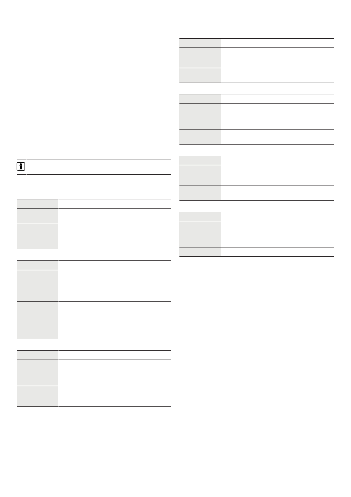
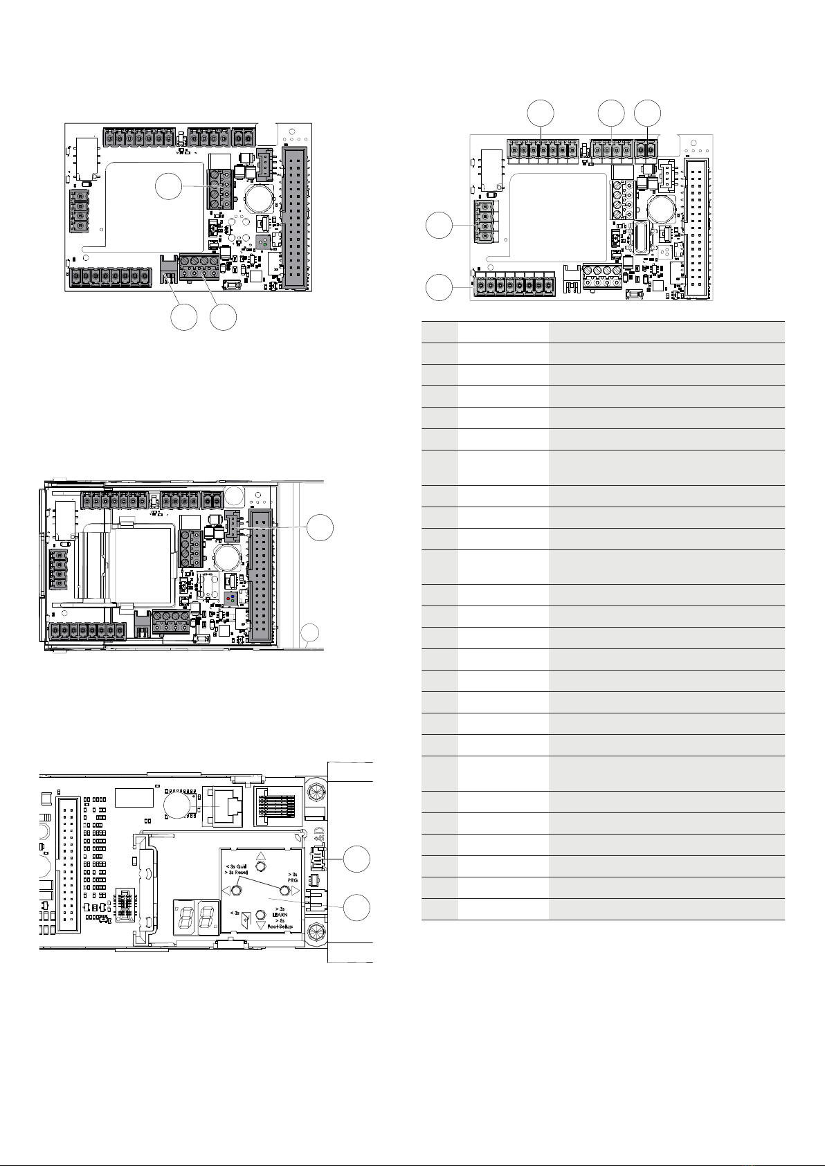
Aufbau der ED-Anschlussplatine-CAN
1 2 3
4
5
6
78910
11
Position Belegung
1 Verriegelung
2 Brandschutz
3 Not-Aus
4 Anschlussbuchse RS232-Schnittstelle
5 Anschlussklemmen CAN-Anschlusskabel Radarsen-
soren M A01
6 RGB-LED-Funktionsanzeige
7 Anschlussbuchse Flachbandkabel
8 Anschlussklemmen CAN-Anschlusskabel EntriWorX
9 Anschlussstecker CAN-Anschlusskabel EntriWorX
10 Sicherheitssensoren
11 Signaleingänge für Nacht/Bank, Impuls außen und
Impuls innen
Für die ED-Anschlussplatine-CAN gelten die Einsatzbedingun-
gen, die in der Montage- und Inbetriebnahmeanleitung für ED
100/250-Antriebe angegeben sind.

ED-CAN
2/8 060634 45532/16923 - 2023-04
LED-Anzeige
Die RGB-LED-Funktionsanzeige auf der ED-Anschlussplatine-CAN ist
als sekundäre Funktionsanzeige definiert. Die RGB-LED-Funktionsan-
zeige zeigt mit Signalfarben den aktuellen Betriebszustand oder ei-
ne Störung an.
Um die Signalfarben der RGB-LED-Funktionsanzeige zu sehen, die
Verkleidung der ED 100/250-Antriebe abnehmen.
Signal
Nr.
Farbe Beschreibung Bedeutung
1 dauer-
haft rot
Anzeige Selbsttest-
fehler
Fehler im Selbsttest
ist aufgetreten oder
CAN-Geräte-erken-
nung ist fehlerhaft.
2 grün
blinkend
Identifikationsanzei-
ge
Die Geräteidentifizie-
rung ist aktiviert.
3 gelb
blinkend
CAN-Gerätezuord-
nung
Die Gerätezuordnung
ist nach einem CAN-
Reset aktiv. Die Gerä-
tezuordnung endet,
wenn die Zuordnung
fehlerfrei abgeschlos-
sen ist oder wenn ein
Fehler auftritt.
4 rot blin-
kend
Fehleranzeige Ein oder mehrere Feh-
ler liegen an. Fehler-
nummer mit höchster
Priorität wird durch
die Anzahl des Blin-
kens angezeigt.
Siehe "Fehler auswerten und Störung beheben".
Signal
Nr.
Farbe Beschreibung Bedeutung
5 weiß
leuchtend
TMS-Initialisierung TMS-Bus-Initialisie-
rung für Sensor und
ED-Anschlussplatine-
CAN läuft.
6 grün leuch-
tend
Anzeige Betriebs-
zustand in Ord-
nung
Das System arbeitet
fehlerfrei.
Aufbau ED 100/250-Antrieb beachten
1 3 4 5 6
8
7
2
In der Grafik ist der ED-Antrieb für den linken Türflügel einer 2-
flügeligen Tür dargestellt. Weitere Hinweise zur Einbaulage und
zu Einstellungen der ED-Antriebe sind in der Montage- und In-
betriebnahmeanleitung für ED100/250 zu finden.
Position Bedeutung
1 Power-On
2 Standard-ED-Anschlussplatine
3 Verkleidung komplett
4 Flachbandkabel
5 RJ45-Steckerbuchse (COM 1)
6 Bedienschnittstelle mit Informationsdisplay
7 Adapter für internen Programmschalter
8 Seitendeckel
Montage
ED-Anschlussplatine-CAN montieren
Den Aufbau der ED-Anschlussplatine-CAN [}] beachten.
1. Den Parameter „C1 -> Konfiguration der Schnittstelle COM1
(stehender Stecker)” auf „1” stellen.
2. Den ED-Antrieb am Gangflügel ausschalten (Netzschalter auf
"0").
3. Die Verkleidung (3) vom Gangflügel-Antrieb abnehmen, siehe
"Aufbau ED 100/250-Antrieb beachten [}]".
4. Das Flachbandkabel (4) aus der Standard-ED-Anschlussplatine
(2) herausziehen, siehe "Aufbau ED 100/250-Antrieb beachten
[}]".
5. Die Stecker von der Platine abziehen.
6. Die Rastelemente in der vorgeschlagenen Reihenfolge nach in-
nen drücken und die Standard-ED-Anschlussplatine (2) heraus-
nehmen, siehe Aufbau ED 100/250-Antrieb beachten [}]".
1.
2.
2.
7. Die Leitungsenden der Anschlusskabel von innen an den unbe-
setzten Platinen-Steckplatz heranführen.
8. Die ED-Anschlussplatine-CAN über die Rastelemente stecken.
9. Die Stecker aufstecken und die Leitungen anschließen.
10. Das offene Leitungsende jedes CAN-Anschlusskabels durch die
mittlere Öffnung in der ED-Anschlussplatine-CAN herausziehen.

ED-CAN
060634 45532/16923 - 2023-04 3/8
11. Das CAN-Anschlusskabel an die Anschlussklemmen (5) für den
Radarsensor M A01 anschließen, siehe auch
Montageanleitung Radarsensor M A01.
Das CAN-Anschlusskabel an die Anschlussklemme für Entri-
WorX (8) anschließen, siehe auch EntriWorX Anleitung.
Das CAN-Anschlusskabel an den Anschlussstecker für Entri-
WorX (9) anschließen, siehe auch EntriWorX Anleitung.
5
89
12. Die offenen Leitungsenden aller weiteren Kabel herausziehen
und anschließen.
13. Alle weiteren Kabel gemäß der Montage- und Inbetriebnahme-
anleitung für ED100/250 anschließen.
14. Das Flachbandkabel wieder in die Anschlussbuchse (7) ste-
cken, siehe "".
15. Das serielle Verbindungskabel in die Anschlussbuchse (4) ste-
cken.
4
16. ACHTUNGAlle Leitungen innerhalb des Antriebs in den Kabel-
kanälen führen/verstauen oder mit einem Kabelhalter befesti-
gen, um Kollisionen mit beweglichen Teilen zu verhindern!
17. Den RJ45-Stecker des seriellen Verbindungskabels in die
Steckerbuchse (5) neben der Bedienschnittstelle (6) stecken,
siehe "Aufbau ED 100/250-Antrieb beachten [}]".
6
5
4
ðDie ED-Anschlussplatine-CAN ist zur Inbetriebnahme ange-
schlossen.
18. Bei 2-flügeligen Anlagen den Adapter (6) für internen Pro-
grammschalter aufstecken.
19. Den externen Programmschalter mit dem Adapter verbinden.
Anschluss
35 41 42 3
1631 4 4a
31G63
62
64343
3111317151 13
1 2 3
10
11
Nummer Zuordnung
1 43 Verriegelungsrückmeldung
3 GND
64 NC
63 NO
62 COM
1G + 24 V geschaltet in Abhängigkeit vom
Rauchmelder
3 GND
2 1 + 24 V
3 GND
6 Upgrade-Card Brandschutz
18k oder RM-ED
1
3 4 Abschaltung Antriebsfunktion
4a GND
10 1 + 24 V
15 Signaleingang Sicherheitssensor Bandsei-
te
17 Test-Ausgang
3 GND
1 + 24 V
11 Signaleingang Sicherheitssensor Bandge-
genseite
13 Test-Ausgang
3 GND
11 35 Signaleingang Nacht/Bank
41 Signaleingang Impuls außen
42 Signaleingang Impuls innen
3 GND
ED-CAN
4/8 060634 45532/16923 - 2023-04
Inbetriebnahme
Voraussetzungen
An der Bedienschnittstelle des EDs muss der folgende Parameter
eingestellt sein:
• Der Parameter „C1 -> Konfiguration der Schnittstelle COM1
(stehender Stecker)” ist auf „1” gestellt.
Falls die Platine vorher schon mal anderswo im Einsatz war, ist zu-
sätzlich ein CAN-Reset nötig, um die alten CAN-Teilnehmer aus dem
Speicher zu "löschen" (Fehler-Nr. 3).
1. Den ED-Antrieb am Gangflügel einschalten (Netzschalter auf
"1").
2. Ggf. den Parameter „Cr -> CAN-Reset" auslösen und den Wert
auf "1" setzen.
ðNach ca. 30 Sek. wechselt die Farbe der LED von weiß auf
grün.
Störungsbehebung
Fehleranzeige
Die Fehlernummer wird durch die Anzahl des Blinkens ange-
zeigt. Es wird die Meldung mit der höchsten Priorität angezeigt.
Die LED-Funktionsanzeige auf der ED-Anschlussplatine-CAN zeigt
die folgenden Fehler an.
Fehler-Nr. 1
Name Fehler TMS Kommunikation
Beschreibung Die Kommunikation zwischen ED-Steuerung und
ED-Anschlussplatine-CAN ist unterbrochen.
Behebung Einstellung Parameter C1 an der ED-Steuerung
prüfen, Verbindungskabel zwischen ED-Steue-
rung und ED-Anschlussplatine-CAN prüfen.
Ggf. Power-On am ED-Antrieb betätigen.
Fehler-Nr. 2
Name Fehler CAN Initialisierung
Beschreibung Bei der Adressvergabe für den Radarsensor
über CAN-Protokoll ist ein Fehler aufgetreten,
da erwartete Antworten ausgeblieben sind.
Dies betrifft die Bus-Kommunikation mit Radar-
sensor.
Behebung CAN-Anschlusskabel und Bus-Terminierung
prüfen, d. h. der DIP-Schalter muss an Pos 4
auf ON/"Abschlusswiderstand für CAN aktiv"
stehen. Anschließend Power-On am ED-Antrieb
betätigen und danach einen CAN-Reset aus-
führen.
Fehler-Nr. 3
Name Fehler unbekannter CAN Bus Teilnehmer
Beschreibung Bei der Gerätezuordnung wurden unbekannte
CAN-Geräte erkannt oder die maximal definier-
te Teilnehmerzahl überschritten. Dies betrifft
die Bus-Kommunikation mit Radarsensor.
Behebung Angeschlossene Geräte auf Richtigkeit prüfen
und ggf. vom Bus entfernen. CAN-Reset aus-
führen.
Fehler-Nr. 4
Name Fehler Gerätezuordnung
Beschreibung Bei der Gerätezuordnung kommen Geräteposi-
tionen doppelt vor. Dies betrifft die Bus-Kom-
munikation mit Radarsensor.
Behebung Einstellung der DIP-Schalter an den Radarsen-
soren prüfen. CAN-Reset ausführen.
Fehler-Nr. 5
Name Fehler fehlendes Gerät
Beschreibung Ein angelerntes Gerät (Radarsensor) ist nach
Einschalten des Systems nicht mehr vorhan-
den. Dies betrifft die Bus-Kommunikation mit
Radarsensor.
Behebung CAN-Anschlusskabel und Geräte prüfen.
Power-On am ED-Antrieb betätigen.
Fehler-Nr. 6
Name Fehler CAN Kommunikation
Beschreibung Die Kommunikation zwischen dem Radarsensor
und der ED-Anschlussplatine-CAN ist unterbro-
chen.
Behebung CAN-Anschlusskabel prüfen. Ggf. Power-On
am ED-Antrieb betätigen.
Fehler-Nr. 7
Name Fehler Radar-Sensor
Beschreibung Ein Gerät (Radarsensor) sendet eine Emergen-
cy-Botschaft aufgrund eines internen Fehlers.
Dies betrifft die Bus-Kommunikation mit Radar-
sensor.
Behebung Power-On am ED-Antrieb betätigen.

EN
ED-CAN
060634 45532/16923 - 2023-04 5/8
Information about this document
Contents and purpose
This Quick Start Guide’s contents are an excerpt from the complete
manual limited to important information about the product and its
commissioning. The complete manual can be accessed using the
QR code.
Target group
The product may only be mounted and commissioned by a quali-
fied electrician.
Safety
WARNING
Danger due to failure of protective and safety equipment
The cable routing connects the installed components with each
other. Unprotected cable routing can lead to tampering or mal-
functions.
• Lay cables either flush-mounted or
• surface-mount the cables in the steel hose
NOTICE
Material damage due to electrostatic discharge
The component can be damaged by electrostatic discharge!
• Ground your body before touching the component.
• Use ESD safe tool.
Product description
Product description
The ED connection board CAN is a board that is required to make
an ED100/250 CAN-capable. It replaces the standard plate in ED
and is compatible from firmware V2.9.000 and up.
Technical data
Supply
voltage
24 V DC +/- 15 %
Power consumption approx. 20 mA quiescent
current
Temperature range -15°C to +50°C
Rel. humidity up to 93%, non-condensing
ED protection class IP20
Dimensions Length 88 mm
width 60 mm
height 26 mm
Structure of the ED connection board CAN
1 2 3
4
5
6
78910
11
Position Layout
1 Locking device
2 Fire protection
3 Emergency stop
4 RS232 interface connection socket
5 Radar sensors M A01 CAN connection cable con-
nection terminals
6 RGB LED function display
7 Ribbon cable connection socket
8 CAN connection cable EntriWorX connection termi-
nals
9 CAN connection cable EntriWorX connection plug
10 Safety sensors
11 Signal inputs for night/bank, impulse outside and
impulse inside
The operating conditions specified in the mounting and com-
missioning instructions for ED 100/250 operators apply to the
ED connection board CAN.

ED-CAN
6/8 060634 45532/16923 - 2023-04
LED display
The RGB LED function display on the ED connection board CAN is
defined as a secondary function display. The RGB LED function dis-
play uses signal colors to show the current operating status or a
fault.
To see the signal colors of the RGB LED function display, remove
the ED 100/250 operators’ cladding.
Signal
no.
Color Description Meaning
1 perma-
nently
red
Self-test error dis-
play
Self-test error oc-
curred or CAN device
detection is faulty.
2 Flashing
green
Identification dis-
play
The device identifica-
tion is activated.
3 Flashing
yellow
CAN device map-
ping
The device assign-
ment is active after a
CAN reset. Device as-
signment ends when
the assignment is
completed without
errors or when an er-
ror occurs.
4 Flashing
red
Error display One or more errors
are pending. Error
number with the high-
est priority is indi-
cated by the number
of flashes.
See “Evaluate errors and rectify faults”.
Signal
no.
Color Description Meaning
5 Glowing
white
TMS initialization TMS bus initialization
for sensor and ED
connection board
CAN running.
6 Green
light:
Display operating
status OK
The system is work-
ing without errors.
Note the structure of the ED 100/250 drive
1 3 4 5 6
8
7
2
The graphic shows the ED operator for the left door leaf of a 2-
leaf door . Further information on the installation position and
settings of the ED operators can be found in the mounting and
commissioning instructions for the ED 100/250.
Position Meaning
1 Power on
2 Standard ED connection board
3 Complete cladding
4 Ribbon cable
5 RJ45 socket (COM 1)
6 User interface with information display
7 Adapter for internal program switch
8 Side cover
Mounting
Mounting the ED connection board CAN
Note Structure of the ED connection board CAN [}].
1. Set the parameter "C1 -> Configuration of the COM1 interface
(vertical plug)" to "1".
2. Switch off the ED operator on the active door leaf (power
switch to "0").
3. Remove the cladding (3) from the active door leaf operator,
see “Note the structure of the ED 100/250 drive [}]”.
4. Pull the ribbon cable (4) out of the standard ED connection
board (2), see “Note the structure of the ED 100/250 drive [}]".
5. Remove the plug from the board.
6. Press the locking elements inwards in the suggested order and
remove the standard ED connection board (2), see “Note the
structure of the ED 100/250 drive [}]”.
1.
2.
2.
7. Insert the cable ends of the connection cables from the inside
to the empty board slot.
8. Plug the ED connection board CAN over the locking elements.
9. Plug in the plugs and connect the lines.
10. Pull the open cable end of each CAN connection cable out
through the middle opening in the ED connection board CAN.
11. Connect the CAN connection cable to the connection termi-
nals (5) for the radar sensor M A01, see also
Radar sensor M A01 mounting instructions.
Connect the CAN connection cable to the connection terminal
ED-CAN
060634 45532/16923 - 2023-04 7/8
for EntriWorX (8), see also EntriWorX manual.
Connect the CAN connection cable to the connector plug for
EntriWorX (9), see also EntriWorX manual.
5
89
12. Pull out the open cable ends of all other cables and connect
them.
13. Connect all other cables according to the mounting and com-
missioning instructions for the ED100/250.
14. Plug the ribbon cable back into the connection socket (7), see
"".
15. Insert the serial connection cable into the connection socket
(4).
4
16. NOTICE!Guide/stow all cables inside the operator in the cable
ducts or secure with a cable holder to prevent collisions with
moving parts!
17. Plug the RJ45 plug of the serial connection cable into the
socket (5) next to the user interface (6), see “Note the struc-
ture of the ED 100/250 drive [}]”.
6
5
4
ðThe ED connection board CAN is connected for commis-
sioning.
18. For 2-leaf units, attach the adapter (6) for internal program
switch.
19. Connect the external program switch to the adapter.
Connection
35 41 42 3
1631 4 4a
31G63
62
64343
3111317151 13
1 2 3
10
11
Number Assignment
1 43 Locking feedback
3 GND
64 NC
63 NO
62 COM
1G + 24 V switched depending on the smoke
detector
3 GND
2 1 + 24V
3 GND
6 Fire protection upgrade card
18k or RM ED
1
3 4 Shutdown drive function
4a GND
10 1 + 24V
15 Signal input safety sensor hinge side
17 Test output
3 GND
1 + 24V
11 Signal input safety sensor opposite side
to the hinge
13 Test output
3 GND
11 35 Signal input night/bank
41 Signal input impulse outside
42 Signal input pulse inside
3 GND

ED-CAN
8/8 060634 45532/16923 - 2023-04
Commissioning
Requirements
The following parameters must be set at the ED user interface:
• The parameter "C1 -> Configuration of the COM1 (vertical
plug) interface” is set to "1".
If the board has previously been used elsewhere, a CAN reset is
also required to "delete" the old CAN participants from the memory
(error no. 3).
1. Switch on the ED operator on the active door leaf (power
switch to "1").
2. If necessary, trigger the "Cr -> CAN reset" parameter and set
the value to "1".
ðAfter approx. 30 secs the LED color changes from white to
green.
Troubleshooting
Error display
The error number is indicated by the number of flashes . The
message with the highest priority is displayed.
The LED function display on the ED connection board-CAN indicates
the following error.
Error no. 1
Name TMS communication error
Description The communication between ED control unit
and ED connection board CAN is interrupted.
Fix Check the C1 parameter setting on the ED con-
trol unit, check the connection cable between
the ED control unit and the ED connection
board CAN. If necessary, actuate Power on on
the ED operator.
Error no. 2
Name CAN initialization error
Description An error occurred when assigning the address
for the radar sensor via the CAN protocol be-
cause the expected responses were not re-
ceived. This affects the bus communication
with the radar sensor.
Fix Check CAN connection cable and bus termina-
tion, i.e. the DIP switch must be set to ON/"ter-
minating resistor for CAN active" at position 4.
Then operate Power-On on the ED operator
and then perform a CAN reset.
Error no. 3
Name Unknown CAN bus participant error
Description Unknown CAN devices were detected during
device assignment or the maximum defined
number of participants was exceeded. This af-
fects the bus communication with the radar
sensor.
Fix Check connected devices for correctness and,
if necessary, remove them from the bus. Exe-
cute CAN reset.
Error no. 4
Name Device assignment error
Description Device positions appear twice in the device as-
signment. This affects the bus communication
with the radar sensor.
Fix Check the setting of the DIP switches on the
radar sensors. Execute CAN reset.
Error no. 5
Name Missing device error
Description A trained device (radar sensor) is no longer
available after switching on the system. This
affects the bus communication with the radar
sensor.
Fix Check CAN connection cables and devices.
Actuate Power on on the ED operator.
Error no. 6
Name CAN communication error
Description The communication between the radar sensor
and the ED connection board CAN is inter-
rupted.
Fix Check the CAN connection cable. If necessary,
actuate Power on on the ED operator.
Error no. 7
Name Radar sensor error
Description A device (radar sensor) sends an emergency
message due to an internal error. This affects
the bus communication with the radar sensor.
Fix Actuate Power on on the ED operator.
Indice
Lingue:
Altri manuali Dormakaba Unità di controllo

Dormakaba
Dormakaba SCU-DR Guida utente

Dormakaba
Dormakaba SIO-DR Manuale utente

Dormakaba
Dormakaba ED connection board CAN Manuale utente

Dormakaba
Dormakaba SafeRoute SCU-UP Manuale utente

Dormakaba
Dormakaba SLI-A Interlock Manuale utente

Dormakaba
Dormakaba LA GARD 700 Series Manuale utente

Dormakaba
Dormakaba UNIQUIN Manuale utente

Dormakaba
Dormakaba MFC Manuale utente
Manuali Unità di controllo popolari di altre marche

Festo
Festo Compact Performance CP-FB6-E Manuale elenco delle parti

Elo TouchSystems
Elo TouchSystems DMS-SA19P-EXTME Manuale utente

JS Automation
JS Automation MPC3034A Manuale utente

JAUDT
JAUDT SW GII 6406 Series Guida rapida

Spektrum
Spektrum Air Module System Manuale utente

BOC Edwards
BOC Edwards Q Series Manuale utente


