Electronics International Inc SR-8A Manuale utente
OI 020481 and II 012881
Electronics International Inc. ®
Smart Engine Analyzer
(SR-8A)
Operating and Installation Instructions
S0210921
1/28/88
Rev. C: 2/2/93 *
63296 Powell Butte Highway Bend OR 97701 (541) 31 -6060
You must read this manual before installing or operating the instrument.
Model:
S/N:

Important Notice
***** MUST READ *****
If you think it is not important to read this manual, you're wrong! This manual
contains important installation information that may affect the safety of your air-
craft, delay your installation or affect the operation of your instrument. You Must
read this manual prior to installing your instrument. Any de iation from these
installation instructions is the sole responsibility of the installer/pilot and may
render the STC in alid.
Read the Warranty / Agreement. There is information in the Warranty / Agreement that may alter
your decision to install this product. If you do not accept the terms of the Warranty / Agreement, do not
install this product. This product may be returned for a refund. Contact Electronics International inc. for
details.
Check that the instrument make and model marked on the side of the instrument and on the invoice are
correct before starting the installation.
It is possible for any instrument to fail thereby displaying inaccurate high, lo or jumpy readings.
Therefore, you must be able to recognize an instrument failure and you must be proficient in operating your
aircraft safely in spite of an instrument failure. If you do not have this kno ledge, contact the FAA or a
local flight instructor for training.
The ability for this product to detect a problem is directly related to the pilots interpretation and
observation skills.
The pilot must understand the operation of this product before flying the aircraft. Do not allo anyone
to operate the aircraft that does not kno the operation of this product. Keep the Operating Manual in the
aircraft at all times

Contents
Warranty ------------------------------------------------------------------------------ 2
Operating Instructions: ------------------------------------------------------------ 3
Introduction ---------------------------------------------------------------------------------- 3
Features --------------------------------------------------------------------------------------- 3
Operating T e Smart Analyzer in Your Aircraft ---------------------------------------- 6
Installation Instructions: ----------------------------------------------------------- 9
1. Important Information and Initial Check Out -------------------------------------------- 9
2. Instrument Setup ------------------------------------------------------------------------ 9.5
3. CHT Probe Installation ----------------------------------------------------------------- 10
4. EGT Probe Installation ----------------------------------------------------------------- 11
5. TIT Probe Installation ------------------------------------------------------------------ 11
6. Oil Temperature Probe Installation --------------------------------------------------- 11
7. Carb. Temp. Probe Installation -------------------------------------------------------- 12
8. OAT Probe Installation ---------------------------------------------------------------- 12
9. Mark Eac Extension Cable ----------------------------------------------------------- 12
10. Route T e Circular Connector ------------------------------------------------------- 13
11. Route Eac Extension Cable ---------------------------------------------------------- 13
12. Hook Up Connecting Wires ----------------------------------------------------------- 15
13. Instrument Installation ----------------------------------------------------------------- 15
14. System Ground Test -------------------------------------------------------------------- 15
Troubleshooting Suggestions ------------------------------------------------------ 16
Specifications and Operating Features ----------------------------------------- 18
SR-8A Wiring Diagram ------------------------------------------------------------19
SR-8A Sample Wiring Diagram For Single 6-Cylinder Engine Aircraft - 20
Appendix A - Adding a Channel to the SR-8A -------------------------------- 21
Appendix B - SR-8A Circular Connectors ------------------------------------- 22
STC Information --------------------------------------------------------------------23
1

2
Warranty
1209921
Electronics International Inc. warrants t is instrument and system components to be free from defects in
materials and workmans ip for a period of one year from t e user invoice date. Electronics Interna-
tional Inc. will repair or replace any item under t e terms of t is Warranty provided t e item is returned
to t e factory prepaid.
l. T is Warranty s all not apply to any product t at as been repaired or altered by any person ot er
t an Electronics International Inc., or t at as been subjected to misuse, accident, incorrect wiring,
negligence, improper or unprofessional assembly or improper installation by any person. This warranty
does not cover any reimbursement for any persons time for installation, removal, assembly or repair.
Electronics International retains t e rig t to determine t e reason or cause for warranty repair.
2. T is warranty does not extend to any mac ine, ve icle, boat, aircraft or any ot er device to w ic t e
Electronics International Inc. product may be connected, attac ed, interconnected or used in conjunction
wit in any way.
3. T e obligation assumed by Electronics International Inc. under t is warranty is limited to repair,
replacement or refund of t e product, at t e sole discretion of Electronics International Inc.
4. Electronics International Inc. is not responsible for s ipping c arges or damages incurred under t is
Warranty.
5. No representative is aut orized to assume any ot er liability for Electronics International Inc. in
connection wit t e sale of Electronics International Inc. products.
6. If you do not agree to and accept the terms of this warranty, you may return the product in new
condition, with receipt, within thirty (30) days for a refund.
T is Warranty is made only to t e original user. T IS WARRANTY IS IN LIEU OF ALL OT ER
WARRANTIES OR OBLIGATIONS: EXPRESS OR IMPLIED. MANUFACTURER EXPRESSLY
DISCLAIMS ALL IMPLIED WARRANTIES OF MERC ANTABILITY OR FITNESS FOR A
PARTICULAR PURPOSE. PURC ASER AGREES T AT IN NO EVENT S ALL MANUFAC-
TURER BE LIABLE FOR SPECIAL, INCIDENTAL OR CONSEQUENTIAL DAMAGES, IN-
CLUDING LOST PROFITS OR LOSS OF USE OR OT ER ECONOMIC LOSS. EXCEPT AS
EXPRESSLY PROVIDED EREIN, MANUFACTURER DISCLAIMS ALL OT ER LIABILITY
TO PURC ASER OR ANY OT ER PERSON IN CONNECTION WIT T E USE OR PERFOR-
MANCE OF MANUFACTURERS PRODUCTS, INCLUDING SPECIFICALLY LIABILITY IN
TORT.
.
SR-8
OPERATING INSTRUCTIONS
OI 020481
Rev: A 2/10/92
The Smart Analyzer is easy to operate. You can learn the basic operation of this unit in the first fe minutes of
hands-on operation. Although the Smart Analyzer is simple to operate, its capabilities are numerous. The follo -
ing section ill describe the operating features of the Smart Analyzer and some of its capabilities.
Features
1. Multi-Function Capability:
The Smart Analyzer has 8 channels. For a 6-cylinder engine, the first 6 channels should be used for EGT or
CHT engine analysis. These channels are designated as "Analyzer Channels". The Peak Locate, Hottest
Cylinder Indicator and Differential Warning features are only functional on the analyzer channels. The EGT
Overtemp and Lo temp, TIT Overtemp and Lo temp, and the CHT Overtemp features are functional on all
channels. The Smart Analyzer kno s hich channels are TIT, EGT and CHT regardless of ho it is hooked
up.
Any channel on the Smart Analyzer may be used to measure any temperature (EGT, CHT, TIT, Oil, OAT,
Carb, Induction Air, Cabin Air, Co ling Air, Water, Intercooler, etc.).
3

FeaturesOperating Instructions
A set of s itches on the back of the Smart Analyzer allo s the unit to be set up for a 4 or 6-cylinder engine,
fuel-injected or carbureted engine and to scan 6 or 8 channels (see Installation Instructions for more informa-
tion).
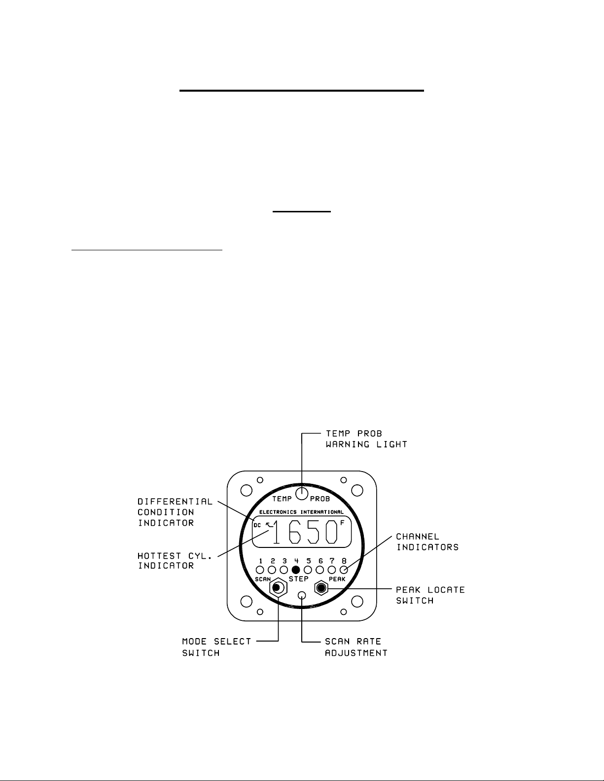
2. Mode Select Switch:
A) Manual Mode - With the Mode Select S itch in the center position, the Smart Analyzer ill display the
temperature on the channel designated by the green Channel Indicators.
B) Step Position - When the Mode Select S itch is pressed to the right, the Smart Analyzer ill advance to
the next channel. When this s itch is released, it ill return to the center position (Manual Mode). The
Smart Analyzer can be set up to step through 6 or 8 channels from the back panel (see Installation Instruc-
tions).
C) Scan Mode - In the Scan Mode, the Smart Analyzer ill automatically scan through the channels. When
the unit is first placed into the Scan Mode, it ill s itch to Channel One to start its scan. This is done to
establish a reference for the automatic engine analysis features.
The Smart Analyzer may be placed in the Scan Mode during runup, takeoff, climb or cruise, as long as the
engine temperatures are increasing or stable. This unique operating characteristic allo s the Smart Analyzer
to stand atch over your engine during most phases of a flight. But if the engine temperatures are decreasing
or lo (as they ould be at idle), the Smart Analyzer should be placed into the Manual Mode of operation to
eliminate any false Lo limit or Differential Condition problems it may find. Generally this only happens
hen the throttle is decreased or you are operating at lo throttle settings.
3. Hottest Cylinder Indicator:
In the Scan Mode, an arro ill appear in the display any time the Smart Analyzer is displaying the hottest
analyzer cylinder. This feature allo s you to determine if the leanest cylinder has changed. If this happens,
you may need to readjust your mixture.
4. "Temp Prob" Warning Light (Automatic Engine Analysis):
A) Manual Mode - In the Manual Mode, if the temperature on the displayed channel exceeds 1650F, the
red Temp Prob arning light over the display ill come on, indicating this is a TIT or EGT channel and it
is over its temperature limit. To eliminate false arnings, all other arning features of the Smart Analyzer
are disabled in the Manual Mode of operation.
B) Scan Mode - In the Scan Mode, all the automatic temperature arning features of the Smart Analyzer
are enabled. The scan ill stop and the Temp Prob arning light ill come on any time one of the follo -
ing problems occurs:
4

Features
5
Operating Instructions
1) Any EGT or TIT channel exceeds 1650F.
2) Any CHT channel exceeds 500F.
3) Any EGT or TIT channel drops belo 1100F.
4) As an EGT analyzer ( hen first 4-6 channels on the SR-8A are used to measure EGT's): Any time
the EGT spread bet een cylinders exceeds 95F for a fuel-injected engine (195F for a carbureted
engine). Also, a DC (Differential Condition) indicator ill appear in the display.
5) As a CHT analyzer ( hen first 4-6 channels on the SR-8A are used to measure CHT's): Any time
the CHT spread bet een cylinders exceeds 95F (may be programmed to 195F). Also, a DC
(Differential Condition) indicator ill appeart in the display.
The Smart Analyzer ill stop on the first channel on hich it finds a problem and light the Temp Prob
arning light. If the problem corrects itself, the Temp Prob arning light ill go out and the Smart
Analyzer ill continue its scan. If the problem is a Differential Condition, the Smart Analyzer ill stop on
the coldest cylinder. In this case, the problem may be the coldest cylinder or it may be the hottest cylinder.
By comparing temperatures ith adjacent cylinders the problem cylinder ill become apparent. To quickly
find the hottest cylinder of the analyzer channels, press the PEAK botton on the front panel.
5. DC Differential Condition Indicator:
In the Scan Mode, any time there is a temperature spread bet een any analyzer channel that exceeds the set
limit, the Smart Analyzer ill stop the scan, light the Temp Prob arning light and a DC ill appear in
the top left corner of the display. This DC indicator ill allo you to distinguish a differential problem
from any other type of problem.
6. Scan Rate Adjustment:
The Scan Rate may be adjusted to suit you (2 to 10 seconds per channel). Using a small, flat tip scre driver,
rotate this adjustment clock ise to increase the time the Smart Analyzer displays each channel. Be careful
not to damage this adjustment. Exert only a light force against the pot hen making an adjustment.
7. Peak Locate Button:
The Peak Locate button may be used in the Manual or Scan Mode of operation. Its purpose is to eliminate all
of the mental calculations and time ordinarily required to find the hottest cylinder of the analyzer channels.
This can be a real asset in leaning or locating a possible problem.
A) Manual Mode - To find the hottest analyzer cylinder in the Manual Mode, press the Peak
button. The Smart Analyzer ill automatically s itch to Channel One and start a fast scan (one
second per channel). It ill scan through all the channels, and on the second pass it ill stop on the
hottest analyzer channel. If during the fast scan the Temp Prob arning light flashes, the Smart

6
Operating Instructions Features
Analyzer has detected a problem but it ill not stop its scan until it reaches the hottest analyzer
channel. (Note: In order to use this feature to lean to an EGT, the first 4-6 channels of the SR-8A
should be used to measure EGT's.)
B) Scan Mode - You may also use the Peak Locate feature in the Scan Mode. Pressing the Peak
button ill start the fast scan on the current channel being displayed and it ill scan until it reaches the
hottest analyzer channel. At that time, it ill continue scanning at the normal scan rate.
8. Back Light and Channel Indicator Intensity:
The Smart Analyzer comes ith 12 and 24 volt digital display back light control lines. The digital display
should be backlit all the time. This ill allo it to easily be vie ed in dim light. The digital display is best
vie ed in high ambient light or direct sunlight.
Also provided is a Green Channel Indicator Intensity Control Line. If this line is connected to your Panel
Light Rheostat, the Green Channel Indicators intensity can be controlled for night operation. As the Panel
Light Rheostat is turned up the Green Channel Indicators ill dim. If you find the Green Channel Indicators
to be too bright during daytime operation, turn the Panel Light Rheostat up slightly to control the intensity of
the Green Channel Indicators to suit your requirements.
Operating The Smart Analyzer in Your Aircraft
1. Taxi:
During taxi the exhaust gas temperatures ill be belo the Lo er Temperature Limits (1100'F). Therefore,
to avoid a red Temp Prob light, operate the Smart Analyzer in the Manual Mode. In the Manual Operating
Mode the Lo er and Differential Limits are disabled.
2. Run Up:
During run up you may ant to look at each of your engine temperatures by stepping the Smart Analyzer
through the channels manually. If you ant the Smart Analyzer to diagnose your engine automatically, place
the Smart Analyzer in the Scan Operating Mode. A situation you may encounter by scanning during run up
is that some of the engine temperatures (such as EGTs) may not exceed their Lo er Temperature Limits
(1100'F). If this is the case, you may ant to check your engine in the manual operating mode.
3. Takeoff:
Place the Smart Analyzer in the Scan Operating Mode during takeoff. For the first fe seconds of the
takeoff roll you may get a red Temp Prob light until the exhaust gas temperatures exceed their Lo er

7
Temperature Limits. The Smart Analyzer ill automatically diagnose your engine during takeoff. A red
Temp Prob light ill alert you if the Smart Analyzer detects a problem during takeoff.
4. Climb:
Leave the Smart Analyzer in the Scan Operating Mode during the entire climb. The Smart Analyzer ill
automatically diagnose your engine during the climb. A red Temp Prob light ill alert you if the Smart
Analyzer detects a problem. One situation that may occur on non-turbo charged aircraft during a climb is a
lo EGT arning. As the aircraft climbs the air gets thinner and the engine ill run richer. When this
happens the exhaust gas temperatures ill drop and may violate the Lo er EGT Limit. Many Smart Ana-
lyzer pilots look for this arning to enable them to properly lean during the climb. If you use this method, do
not allo the exhaust gas temperatures to exceed 1300F for throttle settings above 75% po er. Refer to the
engine and aircraft operator's manual for proper leaning information for your aircraft.
5. Cruise:
In cruise you ill ant to lean your engine. A rich running engine astes fuel needlessly and tends to run on
the rough side, thereby creating vibration, hich causes deterioration of engine accessories and engine
mounts. Also, proper leaning at cruise and during descent means less spark plug fouling, longer life for the
plugs, reduced maintenance costs and a considerable fuel savings. Furthermore, good leaning techniques
result in cleaner combustion chambers ith fe er lead salt deposits on the pistons and exhaust valves. Under
certain conditions, these deposits invite preignition and higher maintenance costs. Proper leaning at cruise
during cool or cold eather aids in raising engine and oil temperatures to desirable minimums in order to
evaporate the ater and acids out of the oil. Water and acids attack the insides of an engine, causing rust and
corrosion.
To properly lean your engine using the first 4-6 channels of the SR-8A to measure EGT's, perform the
follo ing steps:
A) Rough Leaning: Set the Smart Analyzer in the Manual Operating Mode and push the Peak button
belo the EGT display. This feature only functions if you are set up to monitor all of your EGT's on the
first 4-6 channels of the SR-8A. Adjust the mixture control from the full rich position to a leaner setting
that results in a slight drop in engine RPM or to a setting near lean, as dictated by experience. The
mixture control should be left at this setting until the EGTs stabilize. It ill take about 20 seconds for
the temperatures to stabilize ithin 1`F. This lag is due to the combustion alls and piston domes
increasing in temperature and, therefore, affecting the combustion and exhaust gas temperatures. To
correctly lean an engine you must ait for the engine to thermally stabilize. Less sensitive gauges ill
not pick up these subtle changes, hich are important in leaning and diagnosing problems.
B) Precision Leaning: Again press the Peak button on the Smart Analyzer to find the hottest EGT
cylinder. This cylinder may be different than the one you started ith. This is the cylinder on hich
you should perform your precision leaning. Again, start leaning, only this time making very small
Operating The Smart Analyzer in Your AircraftOperating Instru tions

8
adjustments and ait 3 to 5 seconds bet een adjustments. As you approach peak the exhaust gas
temperature ill rise much slo er until it starts to decrease. When this happens you have reached peak
EGT. The 1`F resolution of the digital display ill be invaluable in helping you precisely detect peak
EGT.
C) Finding The Cylinder That Peaks First: For most engines step B (Precision Leaning) ill result in
a properly leaned engine. If you find this to be the case ith your engine, this step ill not be neces-
sary. But if you ant to verify you have leaned to the cylinder that peaks first and your engine is
operating properly, perform the follo ing ith the cylinder found in step B at peak EGT. Slightly
enrich the mixture and quickly step through each cylinder. Any cylinder that sho s a rising temperature
is a leaner cylinder. Check that this cylinder does not rise more than 15F before it starts decreasing in
temperature. If a cylinder rises more than 15F it may have a problem. See our Pilots Manual for
Diagnosing Engine Problems for more information.
The Smart Analyzers unique stable display allo s you to precisely lean to peak EGT or to a specific tem-
perature belo peak for most engines. Peak EGT ith a float-type carbureted engine is frequently a vague
point because of the fuel/air distribution problems in these lo er horsepo er engines. As a result, these
engines tend to operate smoother at 25F on the rich side of peak EGT. The fuel-injected engines ill
provide a more precise peak. Most engines normally operate ithin an EGT range of 1200F to 1600F at
cruise po er.
Some engine manufacturers allo leaning to peak EGT at 75% po er and belo on their direct drive nor-
mally aspirated engines. For your engine, check the engine manufacturers recommended procedures. It is
not recommended to lean for peak EGT above 75% po er settings. The richer mixture is needed to cool the
combustion temperatures and keep the anti-knock capability of the fuel high enough to prevent detonation
from occurring at the higher po er settings.
After leaning place the Smart Analyzer in the Scan Operating Mode. The Smart Analyzer ill automati-
cally and continuously diagnose your engine during the entire cruise portion of your flight. A red Temp
Prob light ill alert you if the Smart Analyzer detects a problem ith your engine.
6. Des ent:
During a long gradual descent the Smart Analyzer may be left in the Scan Operating Mode, but hen the
mixture or throttle control is changed, the engine temperatures ill drop and the Smart Analyzer ill see this
as a problem. Therefore, during this phase of the descent place the Smart Analyzer in the Manual Operating
Mode and select a CHT channel. This ill allo you to look for Shock-Cooling. Any cylinder above 300'F
and decreasing faster than 1'F in 3 seconds is Shock-Cooling.
SR-8A
Operating Instru tions Operating The Smart Analyzer in Your Aircraft
Indice
Altri manuali Electronics International Inc Strumento di misura

Electronics International Inc
Electronics International Inc UBG-16 Manuale utente

Electronics International Inc
Electronics International Inc UBG-16 Manuale utente

Electronics International Inc
Electronics International Inc VA-1A Manuale utente

Electronics International Inc
Electronics International Inc UBG-16 Manuale utente

Electronics International Inc
Electronics International Inc M-1 Manuale utente

Electronics International Inc
Electronics International Inc FP-5L Manuale utente

Electronics International Inc
Electronics International Inc FP-5 Manuale utente


