
Emtron CAN Manuale utente

Z
USER
MANUAL
Rev 1.0
Emtron CAN Gauge
EMTRON ED5 USER MANUAL
WWW.EMTRON.WORLD
© EMTRON AUSTRALIA PTY LTD MARCH 2018
1
Kit Contents
When purchasing the Emtron CAN Gauge the following items are included:
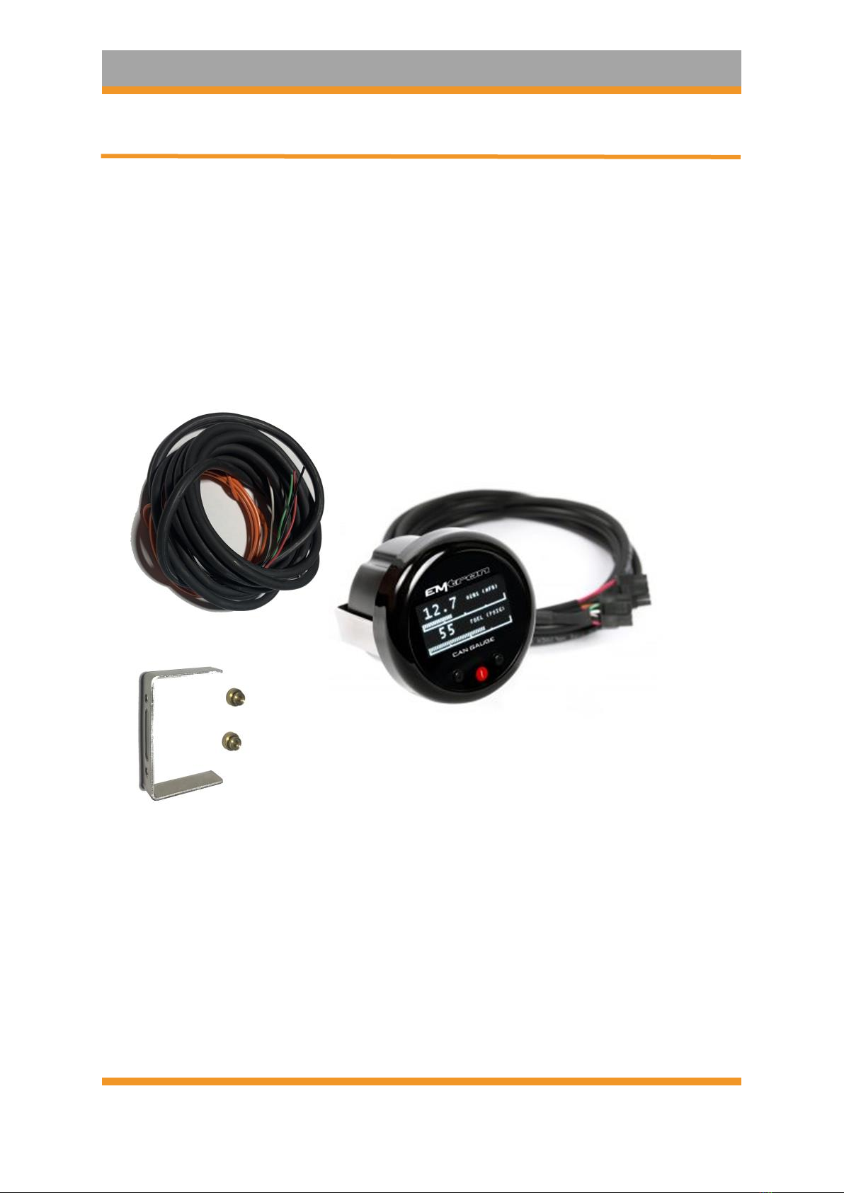
•1x Emtron CAN Gauge
•1 x Mounting Bracket
•2 x Mounting Bracket thumbscrews
•1 x Unterminated standard flying loom

EMTRON ED5 USER MANUAL
WWW.EMTRON.WORLD
© EMTRON AUSTRALIA PTY LTD MARCH 2018
2
Contents
1.0 Description...........................................................................................................................3
2.0 Specification.........................................................................................................................4
3.0 Requirements..................................................................................................................5
3,1 Compatible ECU: ..............................................................................................................5
3.2 Smartphone or Tablet:.....................................................................................................5
3.3 ECU Terminals, Connector, & Installation tools: .............................................................5
4.0 Wiring...................................................................................................................................6
4.1 CAN Guage Wiring............................................................................................................6
4.2 CAN Bus Wiring................................................................................................................7
4.3 Illumination Signal Wiring................................................................................................9
5.0 Gauge ART Application......................................................................................................10
5.1 Create Configuration......................................................................................................10
5.2 Save & Send Configuration ............................................................................................11
5.3 Load Configuration.........................................................................................................11
6.0 Emtune Settings.................................................................................................................12
7.0 Ordering Information.........................................................................................................13

EMTRON ED5 USER MANUAL
WWW.EMTRON.WORLD
© EMTRON AUSTRALIA PTY LTD MARCH 2018
3
1.0 Description
The Emtron CAN Gauge by Gauge ART is a compact 52mm OLED gauge that connects to all
Emtron ECU’s to display real-time data from CAN broadcasts. It is also compatible with
aftermarket and factory ECU’s.
The gauge is wirelessly configurable using an Android or Apple iOS mobile device through
wifi. Gauge channels, bar graphs, warning points, and custom gauge labels can be
configured using the “Gauge ART CAN Gauge App”.

EMTRON ED5 USER MANUAL
WWW.EMTRON.WORLD
© EMTRON AUSTRALIA PTY LTD MARCH 2018
4
2.0 Specification
Emtron CAN Gauge main features summarised:
•52mm display
•Configurable low and high warnings
•Day / Night dimming
•Wireless wifi configuration
•Connect more than one unit
•Runtime channel names user definable
•User defined channels can be displayed
•OLED Display
•1,2 or 4 channel gauge layouts available
•Up to 10 different pages available
Inputs
•1x CAN bus
Operating Temperature
▪Operating Temperature Range: -30 to 85°C (-22 to 185°F)

EMTRON ED5 USER MANUAL
WWW.EMTRON.WORLD
© EMTRON AUSTRALIA PTY LTD MARCH 2018
5
3.0 Requirements
3,1 Compatible ECU:
All Emtron ECU’s are compatible
Most common ECU’s are compatible including:
Adaptronic
AEM EMS 4
AEM EMS Series 2
AEM Infinity
Factory CAN OEM (Requires OBD Link)
Hondata KPro4 / S300
Link G4+
MaxxECU
Megasquirt MS3
Motec M1 Series
ProEFI
Syvecs S6, S6+, S8
Vipec
Wolf EMS
3.2 Smartphone or Tablet:
Smartphone or tablet with Apple iOS or Android v4.4 or later.
3.3 ECU Terminals, Connector, & Installation tools:
The Emtron CAN Gauge includes an unterminated flying loom that will require connection to
a power source and the ECU CAN bus.

EMTRON ED5 USER MANUAL
WWW.EMTRON.WORLD
© EMTRON AUSTRALIA PTY LTD MARCH 2018
6
4.0 Wiring
4.1 CAN Guage Wiring
Wire
Function
Red
14 V Supply
Black
Ground
Orange
14 V Illumination
White
CAN Hi
Green
CAN Lo
Table 4.1. CAN Gauge Wiring

EMTRON ED5 USER MANUAL
WWW.EMTRON.WORLD
© EMTRON AUSTRALIA PTY LTD MARCH 2018
7
4.2 CAN Bus Wiring
The CAN Gauge includes a user-configurable 120 ohm terminating resistor jumper. The
resistor is enabled when the jumper is in place.

EMTRON ED5 USER MANUAL
WWW.EMTRON.WORLD
© EMTRON AUSTRALIA PTY LTD MARCH 2018
8
CAN bus wiring precautions
▪CAN Bus High and Low are differential signals, so twisted pair MUST be used. Failing to
do so will compromise the entire CAN Bus System.
▪In some extreme environments, shielded twisted pair may be required to help with
reliability and data integrity.
▪The less connectors in any transmission system the better. Unnecessary connectors are
almost guaranteed to present an impedance discontinuity and hence may cause
reflections and data loss.
▪CAN Bus termination must be done correctly by using a 120 ohm 0.25W resistor at each
END of the bus system.
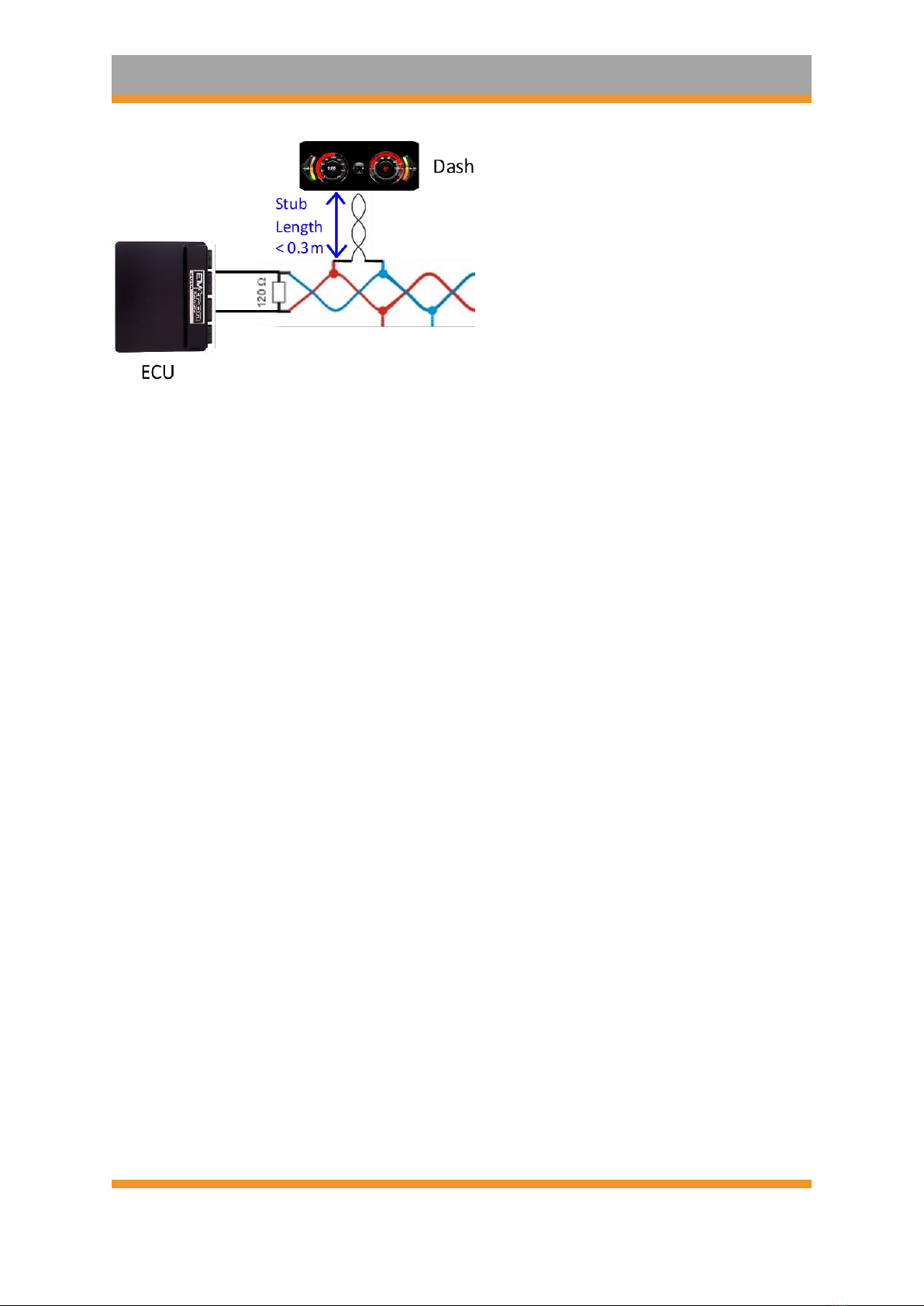
▪Maximum Stub length to a device from the main Bus is recommended at 0.3m, in
accordance with High-Speed ISO 11898 Standard specification. See Figure 3.3.
Figure 4.1. CAN Bus Wiring Example. ECU and Dash at each end with 120 Ohm Termination
Figure 4.2. CAN Bus Wiring Example. ECU and ELC2 at each end with 120 Ohm Termination
EMTRON ED5 USER MANUAL
WWW.EMTRON.WORLD
© EMTRON AUSTRALIA PTY LTD MARCH 2018
9
Figure 4.3. CAN Bus Wiring Example. Stub Length less than 0.3m
4.3 Illumination Signal Wiring
The CAN Gauge can dim illumination during night when the parking lights are on. Using the
factory service manual, find a wire in the interior that switches to +12V power when the
parking lights are on. Verify with a voltmeter or test light that the wire receives +12V when
the parking lights are turned on.
Note that many vehicles have an illumination switched connector in the interior fuse box.
Indice


