Energomera CE308 Manuale utente

СЕ308
Operation Manual
САНТ.411152.107-05.3 РЭ
Manufacturer:
JSC «Electrotechnical factories «Energomera»
415, Lenina Str., Stavropol, Russia 355029
Tel.: (8652) 35-75-27, Fax: 56-66-90,
free Нot line: 8-800-200-75-27
e-mail: concern@energomera.ru
www.energomera.ru
Warranty service:
217, Gagarina Str., Nevinnomyssk,
Stavropol region, 357106
Multifunction
three-phase electricity meter
Case type S31, S34

2

2 3
TABLE OF CONTENTS
1 SAFETY REQUIREMENTS 5
2 METER DESCRIPTION 6
2.1 Meter application 6
2.2 Meter modifications 9
2.3 Certification Information 12
2.4 Normal application conditions: 12
2.5 Operating application conditions 12
2.6 Environmental conditions 13
2.7 Technical specifications 13
2.8 Meter design 19
3 PREPARING THE METER FOR OPERATION 20
3.1 Unpacking 20
3.2 Pre-operation 20
3.3 Installation procedure 20
3.4 Connection diagrams 21
3.5 Lithium cell replacement 35
3.6 Meter configuration 36
4 METER READING 37
4.1 Information displayed on the LCD 37
4.2 Viewing of total accumulations (cumulative total) 40
5 METER VERIFICATION 47
6 MAINTENANCE AND SEALING 48
7 ROUTINE MAINTENANCE 49
8 STORAGE AND TRANSPORTATION CONDITIONS 50

4
9 TRANSPORT AND CONSUMER PACKAGING 50
10 MARKING 51
ANNEX A 53
ANNEX B 54
ANNEX C 56

4 5
This САНТ.411152.107-05.3 РЭ (Operation Manual) contains brief information on CE308 S31, CE308 S34
multifunctional three-phase electricity meter (hereinafter referred to as the "Meter"). Complete information on the
above meter is contained in User Manual, which is available on the manufacturer's website:
www.energomera.ru/ru/products/meters/ce308-all
When meter studying and operating, it is necessary to follow the Technical passport (included in the meter
delivery kit) and User Manual.
Only persons who have received special training for working with voltages up to 1000 V and who have studied
the Operation Manual are allowed to work with the meter.
1 SAFETY REQUIREMENTS
1.1 For operational safety, the meter meets the safety requirements of GOST 22261-94 and IEC 61010-1:2001.
1.2 According to the method of protection against electric shock, the meter corresponds to class II in compliance
with IEC 61010-1:2001.
1.3 The insulation between all current and voltage circuits connected together and with the “ground” can
withstand a voltage of 4 kV AC at 50 Hz for 1 minute. During the test, the leads of the electrical test output device,
the interface circuits are connected to the "ground" (the "ground" is a conductive foil film enclosing the meter and
attached to a flat conductive surface on which the meter base is mounted).
For meters of transformer connection, the insulation withstands a voltage of 4 kV AC at 50 Hz for 1 minute,
when applied between current circuits connected together and voltage circuits connected together.
1.4 For meters of transformer connection, the insulation between each current circuit and all other meter
circuits connected to the "ground"; between each voltage circuit and all other meter circuits, including the common
voltage circuit output connected to the "ground", withstands pulse voltage of 6 kV.
The insulation between all current and voltage circuits connected together and with the "ground" can withstand
pulse voltage of 6 kV. During the test, the leads of the electrical test output device must be connected to the
"ground".

6
1.5 Insulation resistance between the meter case and electrical circuits, at least:
20 MΩ — under conditions of item 2.5;
7 MΩ – at an ambient air temperature (40±2) °С, relative air humidity of 93%.
1.6 The meter must be installed and operated in accordance with the applicable rules for technical operation of
electrical installations.
1.7 Do not put foreign objects on the meter, avoid strikes.
2 METER DESCRIPTION
2.1 Meter application
The meter is three-phase, of transformer or direct connection (depending on modification) device, it is designed
to measure active and reactive electrical energy in three-phase four-wire AC circuits.
The meter has the following functions:
• multi-tariff electricity metering (with three tariffing levels - event-based, external and time-based tariffing);
• event logs (fixation of current values of energy storage: at the end of the billing periods (day, month, year)
and when certain event tiggers);
• load profile storage, with the ability to customize the type of stored parameters and averaging time;
• network parameters measurement: voltage frequency, phase currents, phase voltages, phase to phase (line)
voltages (with non-specified accuracy), angles between current and voltage per phases; power factor per phase
and of three-phase, active, reactive, apparent power per phase and in total;
• Unified Power Quality Index measurement (UPQI) in accordance with class "S" of the measurement process
specifications in IEC 61000-4-30:2008: steady-state voltage deviation, frequency deviation, voltage fall duration
and depth, overvoltage duration, the maximum overvoltage, power supply interruption;
• power quality analysis for compliance with quality standards in accordance with EN50160:2010;
• indication of the individual power quality index violation on the LCD (disabled by default);
• recording the violation of an individual power quality (event logs available for reading on the interface);
• active power consumption monitoring;

6 7
• "instantaneous power" consumption monitoring;
• active energy consumption monitoring (control of energy limits, prepaid mode, low consumption control);
• mains voltage monitoring;
• currents monitoring;
• network frequency monitoring;
• phase sequence monitoring;
• phase break monitoring;
• oncoming power flow monitoring;
• alarm relay (in the meter modifications with an alarm relay (see Table 2.1));
• telemetric outputs with the ability to use them as a "relay";
• interface alarm (the ability to act as an initiator of communication with the level of DCU or HES during: terminal
cover opening; exposure to a magnetic field; reparameterization; maximum power excess; deviation from the
normalized value of voltage level, etc., in accordance with the full list, for details, see the user manual;
• time accounting;
• self-diagnostics;
• information protection;
• tamper detector (electronic seals);
• magnetic field sensor;
• event logs with recording of: terminal cover opening; case opening; dates of last re-programming; magnetic
field effect field causing unacceptable deviations of the meter's metrological characteristics; facts of communication
with the metering device that led to data changes; voltage deviations from the device’s nominal values in the
measuring circuits; results of self-diagnostics; changes in the current values of time and date during time
synchronization (at least 3,500 records using the DLMS/COSEM protocol.), etc., for details, see the user manual;
• flexible adjustment of meter events response;
• DLMS/COSEM exchange protocol support;
• display of information on the LCD accompanied by OBIS codes;

8
• IEC 60870-5-104-2004 exchange protocol support;
• peak demand management according to set TOU.
A detailed description of meter features is given in the full version of User Manual.
The meter may be used in AMR system for measured or calculated parameters transmission to the electric
energy control, metering and distribution dispatch center.
Meters are integrated into the following software products for AMI system bul;ding: "cEnergo", "Pyrimida-Seti",
"Pyramid 2.0", etc. (a complete list of supported software products is available on the manufacturer's website.
Measurement results are drawn by the meter motherboard microprocessor circuit processing and calculating of
the current and voltage input signals. The measured data and other information is displayed on the LCD and could
be transmitted via optical port, via one or two additional interfaces.
The meter has 2 communication channels. The PLC G3 or PLC+RF communication module in metering devices
operates on the principle of a mesh network and provides search for collected data guaranteed transmission
duplicate routes.
The meter has an electronic register that accomplishes, depending on the set current and voltage transformation
ratios, metering of active, reactive electric energy in kW*h and KVAr*h correspondingly, on a cumulative total and
per 8 tariffs in two directions.
Time of register readings changing complies with requirements of IEC 62052-11:2003, IEC 62053-21:2003 ,
IEC 62053-22:2003 and IEC 62053- 22:2003.
* short-term (at least 3 minutes) autonomous operation, for data exchanging with AMI system, in the absence of main and backup power (only in Z1
modifications).

8 9
Built-in communication module designation
Additional options:
See Table 2.1.
Integrated communication interfaces:
See Table 2.1.
Nominal or base (max.) current:
3 – 5(10) А;
5 – 5(60) А;
6 – 5(100) А.
Nominal voltage (phase/line):
0 – 3x57.7/100 V;
4 – 3x230/400 V.
Active/reactive energy accuracy class:
4 – 0.2S/0.5
5 – 0.5S/0.5;
7 – 1/1.
Case type and number:
S31, S34 – for board mounting.
Figure 2.1 — Designation structure
2.2Meter modifications
2.2.1 The structure of meter designation is shown in Fig. 2.1
CE308 XX.XXX.XX.XXX XXXX
10
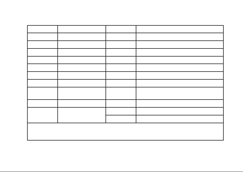
Table 2.1
Designation Interface Designation Additional software and hardware options
O* Optical interface (OI) S Alarm relay
B M-BUS Q Load control relay
E EIA-232 Y Bidirectional metering
A EIA-485 D External display
PPLC U Power quality parameters
G GSM V* Electronic seals
N Ethernet J Optional connection of a reserve power supply
R1 RF-interface with built-in
antenna L LCD backlit
T** Pulse inputs
R2 RF-interface with
external antenna
F Magnetic field sensor
Z Extended set of parameters
* - default options for all meter modifications
** - pulse inputs are implemented as part of a metering device or by using an external pulse input expansion
module manufactured by Energomera JSC or similar.
Altri manuali per CE308
1
Indice
Altri manuali Energomera Strumento di misura


