
Energybox Hub Manuale utente

Technical Documentation
│1
Hub/Dot
Installation Manual
Technical Documentation
│2
DOC
Hub Installation Manual
Issue Date
17/10/2018
>>> Change History <<<
Rev
Date
Issued By
Description
1.0
17/10/18
DB
Version 1.0
Prepared by:
DB
Date
17/10/18
Reviewed by:
Objective
The Technical documentation is describing and defining the usage of specified items for technical experts. It shell
describe features of the defined topic, expected performance and examples. Target audience is professional trained
experts only.
Definitions and Abbreviations
Diagram
All diagrams shall be provided in a way that they can be directly transferred into any
relevant Marketing material such as Technical Specifications or User Manual.
Instruction
All instructions shall be formulated or presented in a way that they can be understood by a
third-party layman and used as basis for descriptions in the User Manual

Technical Documentation
│3
Table of Contents
General 5
Introduction 5
Safety Instructions 5
Package content 5
Specification Hub 6
Interfaces 6
Power Compatibility 6
Technical Data 7
Dimensions 8
Installation Hub 9
Mounting Options 9
Mounting on Wall 9
Mounting on Ceiling 10
Setup Hub 11
User Interface (Buttons & LEDs) 11
Network connect 12
IP settings (wired LAN connection) 12
Pairing of wireless Sensors (Dots) 12
Clear Buffer Data 13
Reset RF setting 13
Admin Portal 14
Status page 14
Network page 15
Sensors 15
Setup Dot 16
General 16
Powering Dot 17
Mounting Dot 17
Connecting Sensor Probe 18
Pairing Dot 18
Button / LED 18
Factory reset Dot 19
Dimensions Dot 19
Firmware update 20


Technical Documentation
│5
General
Introduction
The Hub is a central IoT gateway with integrated wireless transmitters to uplink sensor data to the cloud
backend. The Hub can connect to Energybox sensors (Dot) wirelessly and receive sensor data. The
information will be time synchronized and aggregated. Connected to internet via LAN interface or the
internal cellular modem the data can be uplinked to the cloud database.
This document describes how to install a unit and ensure proper operation. Besides general information
you will be guided through the physical installment process and the operation of device and data uplink
connectivity.
Safety Instructions
Please always disconnect power before installing the unit ! Any installation should be done by certified
personnel. Please make sure the unit is not connected to any voltage level outside specification.
Package content
The package contains the following items:
▪Hub
▪Mounting Plate
▪Mounting-Screws
▪Sim card (optional)
▪CAT5 cable (LAN)
▪Antenna for RF connection
▪Antenna for cellular connection
▪AC/DC Power adaptor
▪DC Jack Adaptor for fixed wire mounting on DC cord

Technical Documentation
│6
Specification Hub
Interfaces
PORT
DESCRIPTION
PORT SPECIFICATION
CABLE REQUIREMENTS
1
LAN port
RJ 45 TCP/IP
CAT5 or higher
2
Antenna 4G (green code)
SMA Jack
-
3
USB Port for backup battery
Micro USB
Micro USB cable
4
DC Power port
DC Jack 2.5mm
Adaptor or DC In hole Jack
5
Antenna RF (grey code)
SMA Jack
-
Power Compatibility
The Hub provides various options to power the unit. All of them can be operated simultaneously and
provide fallback feature between each other.
POWER INPUT
DESCRIPTION
PORT SPECIFICATION
POE
Power over Ethernet
LAN RJ45
DC JACK
5V / 2A DC input
AC/DC adaptor required
USB POWER
5V / 2A USB power from battery
power pack for backup of unit
Micro USB; not charging is
provided

Technical Documentation
│7
Technical Data
Build In Powersupply
Power Input DC Power input 5V / 2A, AC-DC Power Adaptor 90-240VAC, 50/60 Hz
PoE via LAN port
USB 5V / 2A battery power pack support (backup function)
Sensor Communication
RF Frequency 902-928 MHz (US version)
Antenna SMA, 3dBi gain
Wireless range 1000 ft / 300m (in line of sight), 150 ft / 45m (indoor)
Range may vary according to environmental variables
Max no of Sensors 50
Security AES-128 Encryption
Network Communication
LAN RJ45 10/100 Mbps
Security TLS1.2, AES-128 Encryption
IP DHCP or static IPv4
Bandwidth min. 128kBps upload speed
4G LTE/4G Modem with dedicated Simcard
Antenna SMA, 3dBi gain
Data Logger
Memory Size 120MB
Capacity Max. 4 weeks
Enclosure
Mounting/Housing Wall or Ceiling mount
Size DIA 7.88” x H 2.21”
DIA 200mm x H56mm
Weight 0.98lbs / 445g
Environmental conditions
Location Indoor Unit
Operating Temp. 32°F to 113°F (0°C to +45°C)
Storage Temp. -22°F to 140°F (-30°C to +60°C ()
Humidity max. 90% non-condensing
Regulatory
FCC

Technical Documentation
│8
Dimensions

Technical Documentation
│9
Installation Hub
Mounting Options
The Hub can be mounted in different options on Wall, Ceiling or Desk. Necessary mounting equipment is
provided as accessory.
Mounting on Wall
Technical Documentation
│10
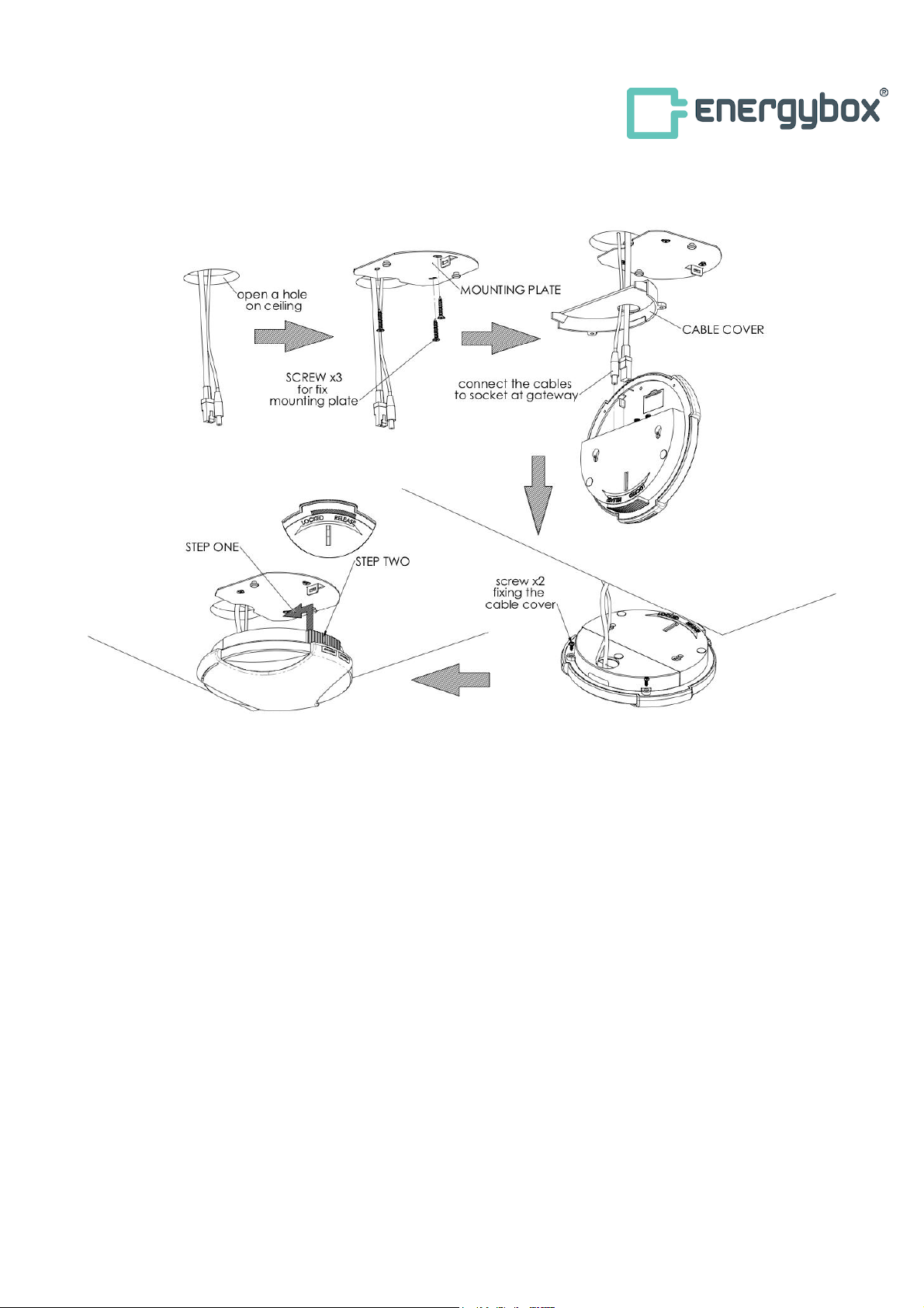
Mounting on Ceiling
Questo manuale è adatto per i seguenti modelli
1
Indice


