Installation and Operation Manual - DustEx Table of Contents
Doc.-ID: COM_OXI_Dust_11022020 1
Table of Contents
1System Description 1
1.1Distinction between COMTEC / OXITEC DustEx 1
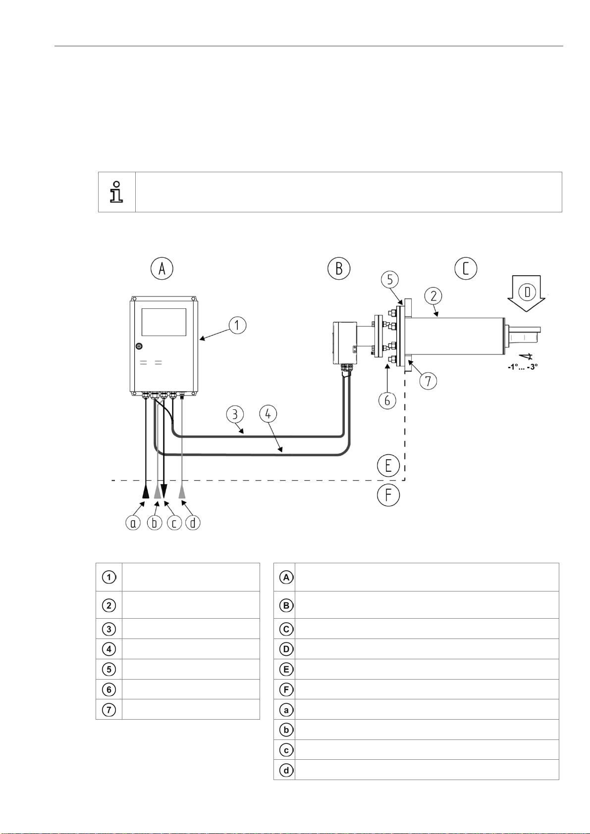
1.2System Overview 1
1.3Measuring principle 2
1.4Intended use 2
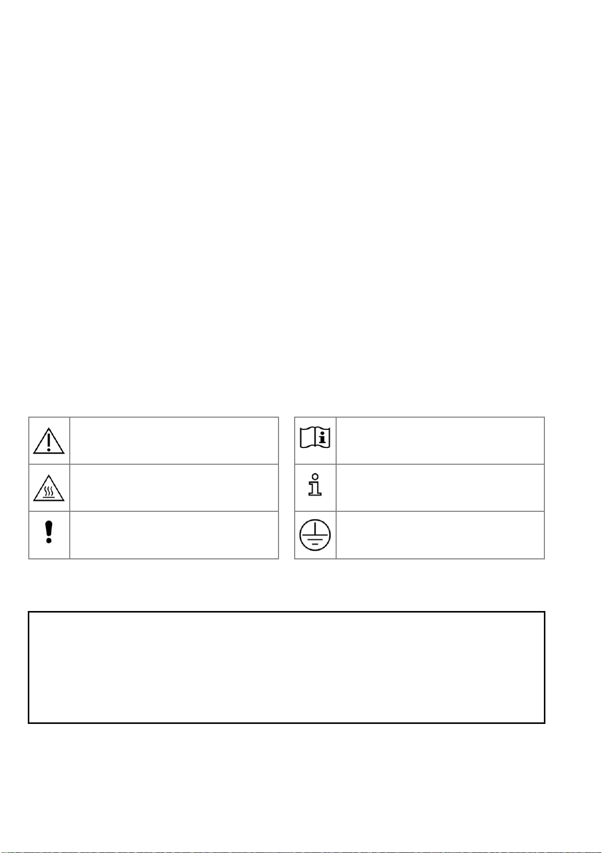
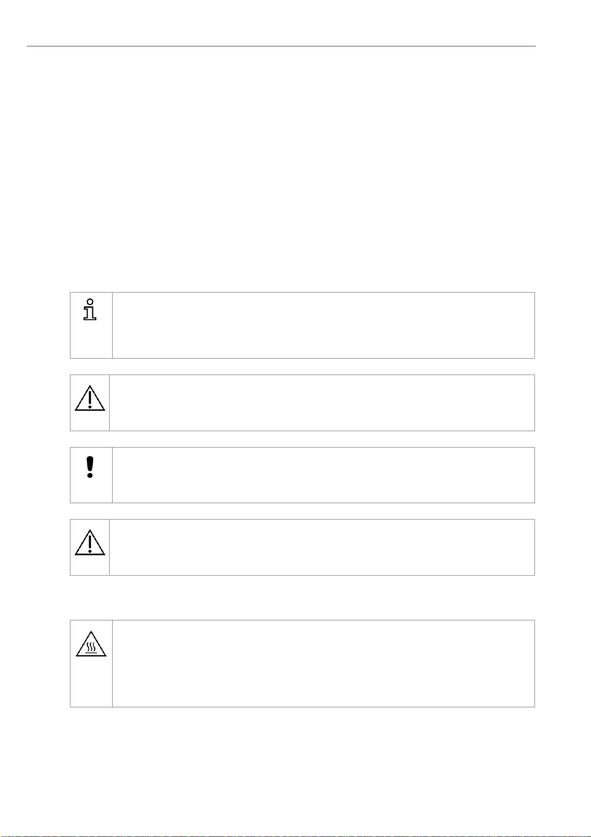
1.5Safety Hazards 2
1.6Disruption of the Process 2
1.8Storage instructions 3
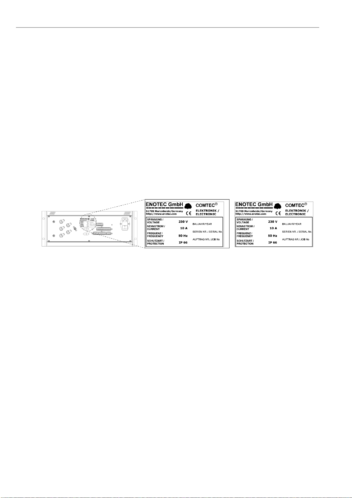
1.9Name Plates 4
2Installation 5
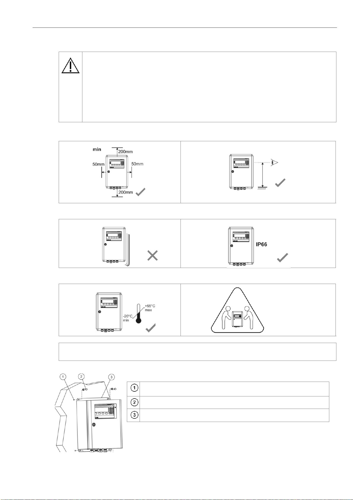
2.1Installation Requirements for Electronic Unit 5
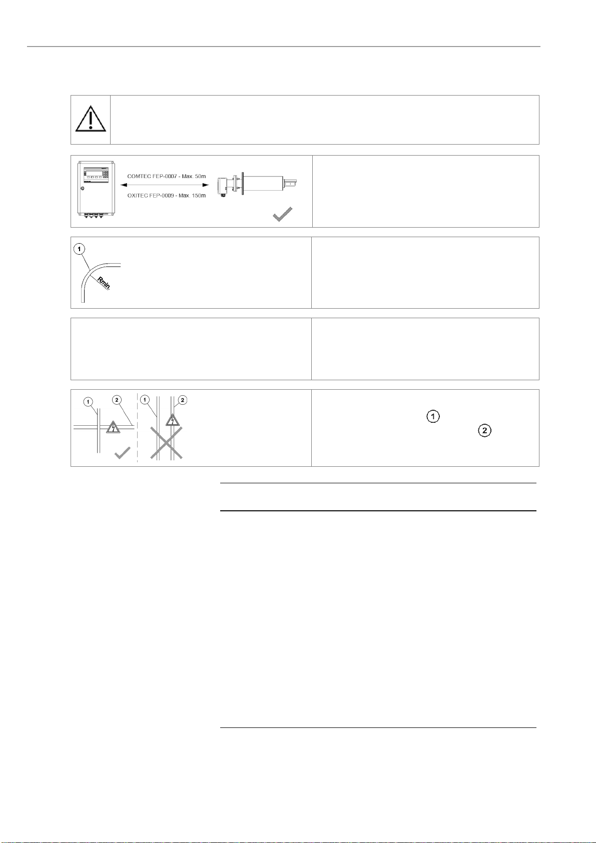
2.2Installation Requirements for Probe Cable 6
2.3Access to the Terminals 7
2.4Fitting of Ferrite Sleeves 7
2.5Wiring Diagram of the Electronic Unit 1
2.6Electrical Wiring Diagram - OXITEC DustEx 2
2.7Electrical Wiring Diagram - COMTEC DustEx 3
2.8Installation of the probe 4
2.9Mounting of the Counter Flange at the Duct 5
2.10Adjusting the V-shield 5
2.11Mounting of the Probe 6
2.12Electrical Connections of the Probe 6
2.13Requirements for Pneumatic Cable FEP-0002 7
2.14Preparation of the pneumatic cable 8
2.15Pneumatic Connections of the Probe 8
2.16Pneumatic Connections of the Electronic Units 1
3Initial Operation 2
3.1Checklist before commissioning the system 2
3.2System Power Up 2
3.3Display - Probe Heating Phase 3
3.4Display - Measuring Mode 3
3.5Keypad and Display 3
3.6Status LEDs 4
3.7Softkey Symbols 4
3.8System Code 4
4Menu Overview and Explanations 5
4.1Menu Overview - SYS-MENU 5
4.2Menu Explanations - SYS-MENU 1
4.2.1O2Measuring Ranges (Scaling) 1
4.2.2Limit alarm settings 1
4.2.3O2Sensor calibration values 1
4.2.4Measuring value averaging for 1
4.2.5mA output on system errors 1
4.2.6COe Measuring Ranges (Scaling) 2
4.2.7COe Sensor Calibration values 2
4.2.8Time per test gas apply 2
4.2.9Delay time to process 2
4.2.10Pre-purge time 2
4.2.11Automatic Calibration (ACAL) 1
4.2.12ENOTEC REMOTE 2
4.2.13Measuring units 2
4.2.14Language 2
4.2.15Change system code 2
4.2.16Load factory settings 3
4.2.17Set COe measurement to off/on 3
4.2.18Service 3
4.3System Checks 4
4.4CAL MENU 5
4.4.1Calibration Menu - Display Overview 5
4.4.21-point calibration (O2and/or COe) (manual) 6
4.4.32-point calibration (O2and/or COe) (manual) 6
5Service and Maintenance 7
5.1Exchange fuses 7
5.2Flow Rates for Test Air and Reference Air 8
5.3Adjusting Flow Rate (SME 53 with integrated
Pneumatics) 8
5.4Position of the adjustment valves 9
5.5Adjusting Flow Rate (SME-54) 9
5.6Replacing the Filter Head 10
5.7Replacing the probe 10
5.8Exchange of Probe Inner Parts 11
5.9Replacing the O2Sensor 12
5.10Replacing the COe Sensor (COMTEC) 13
5.10.1Seal the COe sensor guide tube 14
5.11Relay Outputs / Functions and Correlations 15
5.12Digital Inputs 16
5.13Stability Criteria for Calibration 16
5.14Reaction Time of the mA Output............................16
5.15Extension Modules.................................................16
5.16Maintenance Intervals............................................16
6Status Messages 17
6.1Error Messages......................................................17
6.2Alarm Messages ....................................................19
6.3Service Messages..................................................19
6.4Heater Control Unit ................................................20
7Troubleshooting 21
ATechnical Data 23
A.1Electronic Unit........................................................23
A.2Probe......................................................................24
A.3Requirements for the Gas Supply.......................... 25
BDimension Drawings 26
B.1Dimensions of the Electronic Units ........................26
B.2Probe Dimensions..................................................27
B.3Counter Flange Dimensions...................................28
B.4Probe Components................................................29
B.5Gas plan.................................................................30
CSpare Parts 31
C.1Mounting Plates of the electronic Unit ...................31
C.2Display Board.........................................................32
DWarranty 33
EDeclaration of Conformity 34
Index 36