F&F LE-03MQ Manuale utente
www.fif.com.pl
User manual
v. 4.8 (211029)
F&F Filipowski sp.j.
ul. Konstantynowska 79/81
95-200 Pabianice
Tel./fax (42) 215 23 83, 227 09 71
e-mail: [email protected]m.pl
www.fif.com.pl
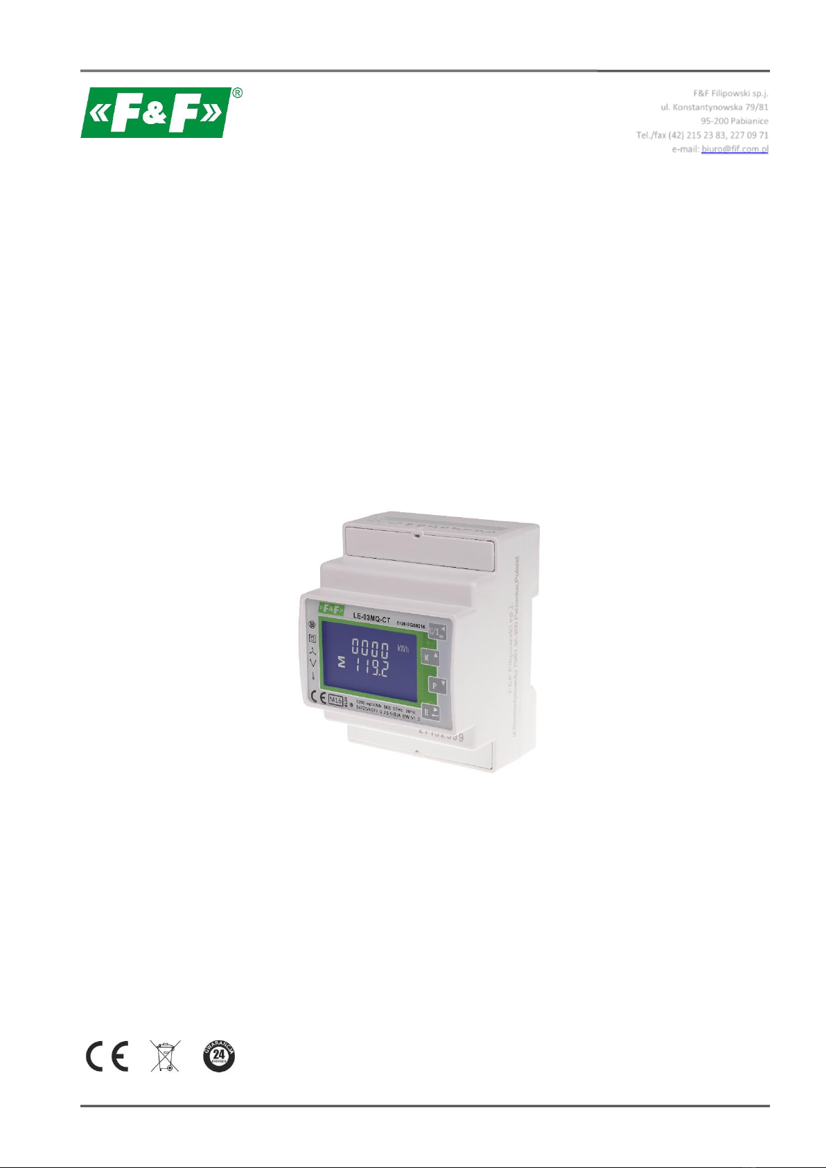
LE-03MQ CT
Electric energy meter
1-phase/ 3-phase
Bidirectional with network parameters analysis

LE-03MQ CT – User manual
2
CONTENTS
1.PURPOSE....................................................................................................................................................... 4
2.UNIT CHARACTERISTIC ............................................................................................................................... 4
2.1. Measured values ............................................................................................................................................................ 4
2.2. Current transformers (CT) .............................................................................................................................................. 4
2.3. RS-485 communication port and Modbus RTU protocole ............................................................................................. 5
2.4. Pulse output .................................................................................................................................................................... 5
3. START-UP SCREENS .................................................................................................................................... 5
4. OPERATOR PANEL ...................................................................................................................................... 6
4.1. Voltage and current, harmonic ...................................................................................................................................... 6
4.2. Frequency, power factor and demand .......................................................................................................................... 7
4.3. Power ............................................................................................................................................................................. 8
4.4. Energy measurements ................................................................................................................................................... 9
5. SETUP ........................................................................................................................................................ 10
5.1. Setup entry methods .................................................................................................................................................... 10
5.1.1. Navigation ............................................................................................................................................................... 10
5.1.2. Number entry procedure ......................................................................................................................................... 10
5.2. Setup parameters ......................................................................................................................................................... 11
5.2.1. Entry into configuration menu ................................................................................................................................ 11
5.2.2. RS-485 communication ............................................................................................................................................ 11
5.2.2.1. (Slave ID) Address ............................................................................................................................................ 11
5.2.2.2. Baud rate ......................................................................................................................................................... 12
5.2.2.3. Parity ................................................................................................................................................................ 13
5.2.2.4. Stop bits ........................................................................................................................................................... 13
5.2.3. Current transformers .............................................................................................................................................. 14
5.2.4. Measuring voltage .................................................................................................................................................. 15
5.2.5. Pulse output ........................................................................................................................................................... 16
5.2.5.1. Energy setup ................................................................................................................................................... 16
5.2.5.2. Pulse rate ........................................................................................................................................................ 17
5.2.5.3. Pulse duration ................................................................................................................................................. 17
5.2.6. Demand Integration Time (DIT) .............................................................................................................................. 18

LE-03MQ CT – User manual
3
5.2.7. Backlit setup ............................................................................................................................................................ 19
5.2.8. Measuring system .................................................................................................................................................... 19
5.2.9. CLR ........................................................................................................................................................................... 20
5.2.10. Change password ................................................................................................................................................... 21
6. TECHNICAL SPECIFICATION ..................................................................................................................... 22
6.1. Measured parameters .................................................................................................................................................. 22
6.1.1. Voltages and currents .............................................................................................................................................. 22
6.1.2. Power factor, frequency and demand ............................. ........................................................................................ 22
6.1.3. Energy measurements ............................................................................................................................................. 23
6.2. Terminal ....................................................................................................................................................................... 23
6.3. Accuracy ....................................................................................................................................................................... 23
6.4. Power supply and power meter .................................................................................................................................... 23
6.5. Measurement inputs .................................................................................................................................................... 23
6.6. Pulse outputs ................................................................................................................................................................ 24
6.7. RS-485 output for Modbus RTU ................................................................................................................................... 24
6.8. Reference conditions of influence quantities ............................................................................................................... 24
6.9. Environment ................................................................................................................................................................. 25
6.10. Structure ..................................................................................................................................................................... 25
6.11. Compliance and sealing .............................................................................................................................................. 25
7. DIMENSIONS ............................................................................................................................................. 26
8. WIRING DIAGRAM .................................................................................................................................... 26
9. MODBUS PROTOCOLE REGISTERS ............................................................................................................. 28
9.1. Input registers ............................................................................................................................................................... 28
9.2. Setup registers ............................................................................................................................................................. 32
8.1. Meter's power supply ................................................................................................................................................... 26
8.2. Measuring systems ....................................................................................................................................................... 27

LE-03MQ CT - User manual
4
1. PURPOSE
LE-03MQ CT is a static (electronic) calibrated electricity meter of single-phase or three-phase
alternating current in a direct system. It is used for reading and recording of consumed
electric energy and mains parameters with remote readout via a wired RS-485 network. The meter
works with current transformers (CT) with 1 A or 5 A secondary current. The configuration of the
meter is done through the configuration menu accessible from the front panel and the
communication port according to the software features of the Modbus RTU protocol.
2. UNIT CHARACTERISTICS
2.1. Measured value
The unit can measure and display:
line voltage and THD% (total harmonic distortion) of all phases
line frequency
currents, current demands and current THD% of all phases
power, maximum power demand and power factor
active energy imported and exported
reactive energy imported and exported
2.2. Current transformers (CT)
The meter works with current transformers (CT) with 1 A or 5 A secondary current.
The appropriate value of rate and the secondary current of the connected
transformer should be set in the meter.
For example: using a 100/5 A current transformer, you should set the secondary
current CT2 to 5 and the rate CTrate to 0020. To get the CT rate to enter you need to
divide a primary current value by the value of the secondary current (100/5 = 20).
WARNING!
The settings for the current ratio (CT2 and CT rate) and voltage ratio
(PT2 and PT rate) can only be made once. It is a legal requirement of
the MID Directive. Once set the rate cannot be changed.
LE-03MQ CT - User manual
5
2.3. RS-485 communication port and Modbus RTU protocole
The meter is equipped RS-485 port with Modbus RTU protocole.
The RS-485 communication port allows you to connect meters into a network of remote reading.
2.4. Pulse output
The meter has two pulse outputs for mapping the counting of active and reactive energy. Output 1
- terminals 9/10 - programmable, can be set to work for active or reactive energy and parameters:
impulsing and pulse length.
Output 2 - Terminals 11/12 - for active energy, impulsing is 3200 pulse / kWh.
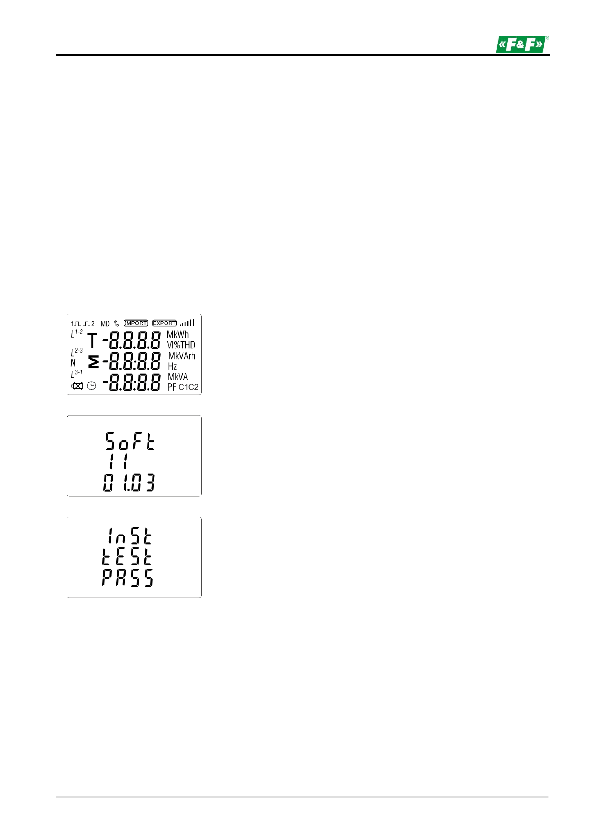
3. START-UP SCREENS
The first screen lights up all display
segments and can be used as a display
check.
Information about software version.
The interface performs a self-test and
indicates the result if the test passes.
LE-03MQ CT - User manual
6
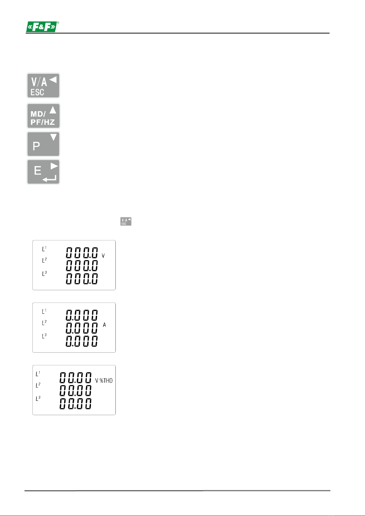
4. OPERATOR PANEL
Buttons features:
Select the voltage and current display screens.
In set up mode, this is the "Left" or "Back" button.
Select the frequency and power factor display screens.
In set up mode, this is the "Up" button.
Select the power display screens.
In set up mode, this is the "Down" button.
Select the energy display screens.
In set up mode, this is the "Enter" or "Right" button.
4.1. Voltage and current, harmonic
Each successive pressing of the button selects a new range:
Phase to neutral voltages (3p4w).
Current on each phase.
Phase to neutral voltage THD% (3p4w).
LE-03MQ CT - User manual
7
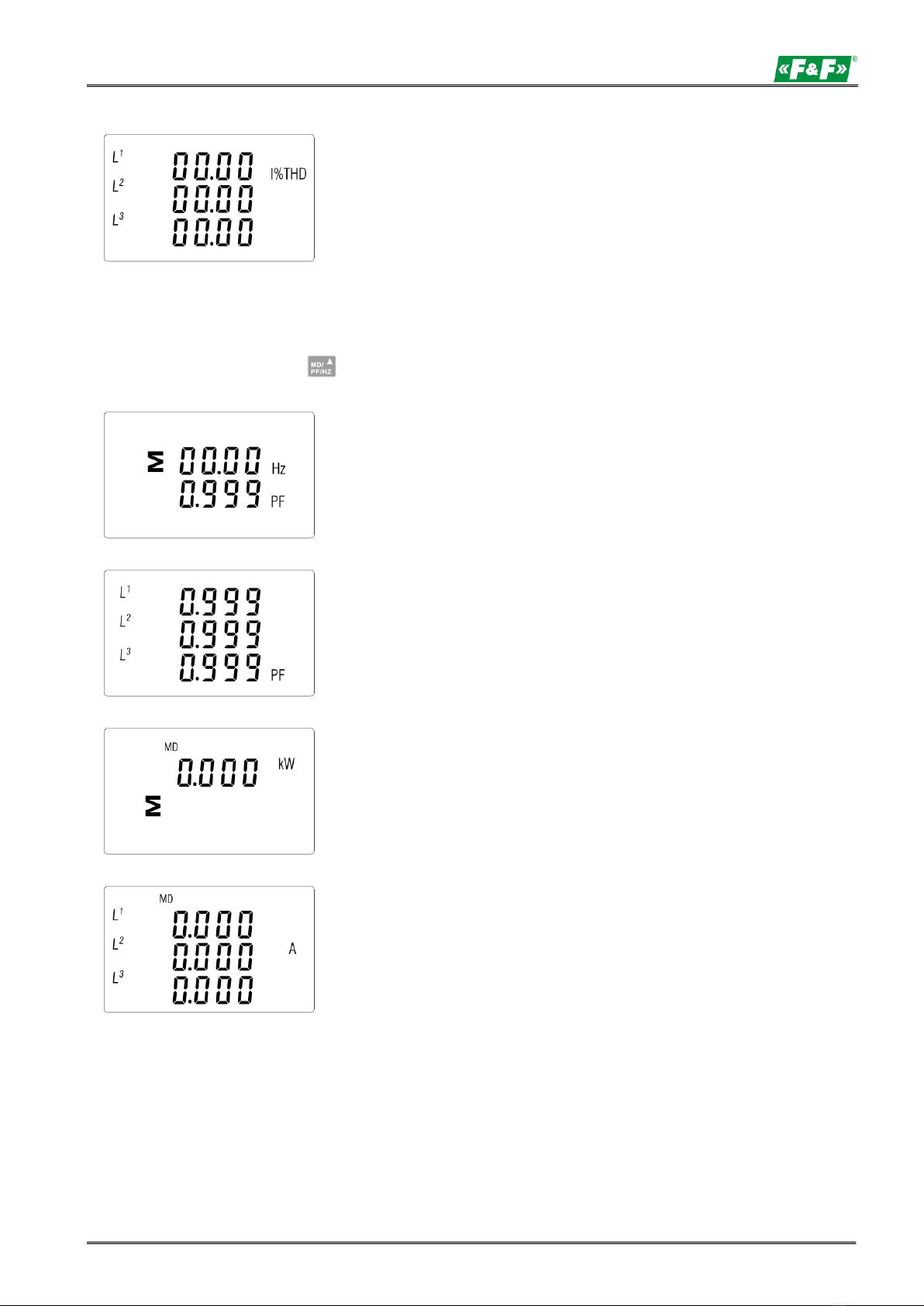
Current THD% for each phase.
4.2. Frequency, power factor and demand
Each successive pressing of the button selects a new range:
Frequency and power factor (total).
Power factor of each phase.
Maximum power demand.
Maximum current demand.
LE-03MQ CT - User manual
8
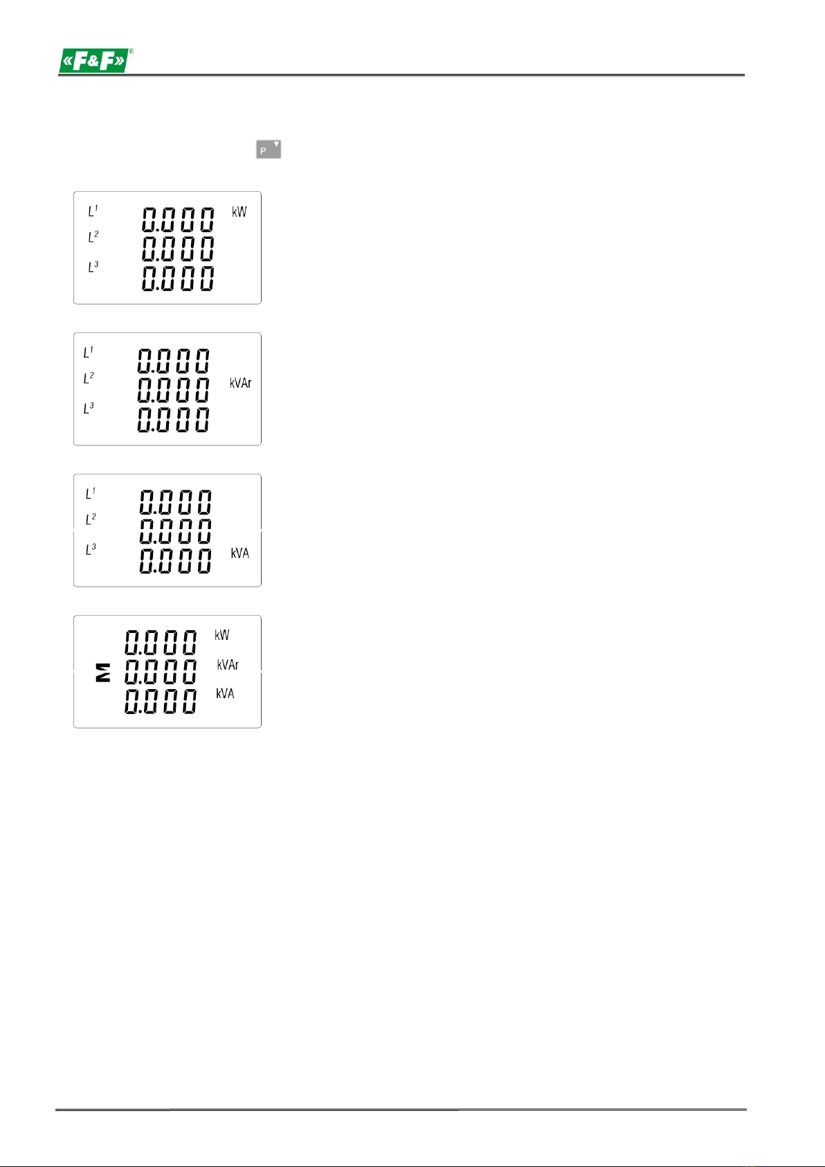
4.3. Power
Each successive pressing of the button select a new range:
Instantaneous active power in kW.
Instantaneous reactive power in kVAr.
Instantaneous volt-amps in kVA.
Total: kW, kvar, kVA
LE-03MQ CT - User manual
9
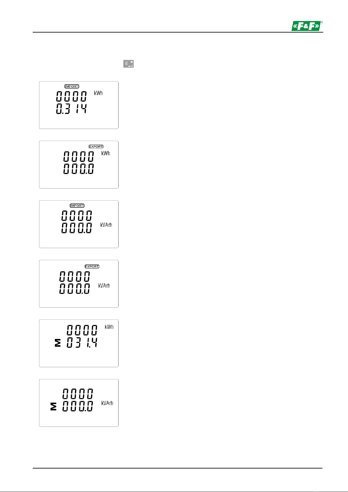
4.4. Energy measurements
Each successive pressing of the button selects a new range:
Imported active energy in kWh
Exported active energy in kWh
Imported reactive energy in kVArh
Exported reactive energy in kVArh
Total active energy in kWh
Total reactive energy in kVArh
The total value of the given energy is presented in two rows.

LE-03MQ CT - User manual
10
The top row presents the higher values, the bottom row presents the lower values + fractional value.
For example:
Indications: 0027 - top row; 845.3 - bottom row presents the value of 27845.3 kWh.
5. SETUP
5.1. Setup entry methods
Some menu items, such as password and CT, require a four-digit number entry while others, such
as supply system, require selection from a number of menu options. After confirming the settings the
meter confirms the adoption of a new parameter by displaying for a moment the word "good".
5.1.1. Navigation
1. Transition to the next position configuration menu.
2. Press to confirm your selection.
3. Edition of value (change of position number by +/- 1)
4. Having selected an option from the current layer, press to confirm your selection. The SET
5.1.2. Number entry procedure
When setting up the unit, some screens require the entering of a nuber. In particular, on entry
to the setting up section, a password must be entered. Digits are set individually, from left to right.
The procedure is as follows:
indicator will appear.
1. The current digit to be set flashes and is set using the and buttons.
2. Press to confirm each digit setting. The SET indicator appears the last digit has been set.
to exit the number setting routine. The SET indicator will be 3. After setting the last digit, press
xxremoved.
5. Back to the higher menu level. The SET indicator will disappear and you will be able to use
the buttons, again to select further options.
6. exit the configuration menu to the measurements screen.
Altri manuali per LE-03MQ
2
Indice
Altri manuali F&F Strumento di misura


F&F
F&F DMA-1 CT TrueRMS Manuale utente

F&F
F&F LE-03MQ Manuale utente

F&F
F&F CLI-01 Manuale utente

F&F
F&F LE-03MW Manuale utente

F&F
F&F LE-03MP Manuale utente

F&F
F&F LE-03MB Manuale utente

F&F
F&F DMA-3 CT TrueRMS Manuale utente

F&F
F&F WZE-3 Manuale utente

F&F
F&F LE-03MW Manuale utente

F&F
F&F LE-03d CT200 Manuale utente


