Fasep RAE.2108 Manuale utente

Qualcuno di cui ti puoi fidare
(Someone you can trust)
{
FASEP 2000 srl
Via Faentina, 96
50030 Ronta (Fi) Italy
Sistema Qualità Certificato ISO 9001:2000
Tel +39 055 8403126 E-mail info@fasep.it
Fax +39 055 8403354 WWW www.fasep.it
˜
FASEP 2000 srl
Via Faentina, 96
50030 Ronta (Fi) Italy
Sistema Qualità Certificato ISO 9001:2000
liam-E6213048 550 93+leT [email protected]
WWW4533048 550 93+xaF www.fasep.it
Instruction Manual - ENG
Version 1.0 - January 2014
RAE.2108
TYRE CHANGER

2 User’s manual
Elaborazione graca e impaginazione
Ufcio Pubblicazioni Tecniche
I
diritti di traduzione, di memorizzazione elettronica, di
riproduzione e di adattamento totale o parziale con qualsiasi
mezzo (compresi microlm e copie fotostatiche) sono riservati.
Le informazioni contenute in questo manuale sono soggette a
variazioni senza preavviso.
All rights of total or partial translation, electronic storage,
reproduction and adaptation by any means (including
microlm and photocopies) are reserved.
The information in this manual is subject to variation without
notice.
Les droits de traduction, de mémorisation électronique, de
reproduction et d’adaptation totale ou partielle par n’importe
quel moyen (y compris microlms et copies photostatiques)
sont réservés.
Les informations contenues dans ce manuel sont sujettes à
des variations sans préavis.
Alle Rechte der Übersetzung, elektronischen Speicherung,
Vervielfältigung und Teil- oder Gesamtanpassung unter
Verwendung von Mitteln jedweder Art (einschließlich Mikrolm
und fotostatische Kopien) sind vorbehalten.
Die im vorliegenden Handbuch enthaltenen Informationen
können jederzeit ohne Vorankündigung geändert werden.
Quedan reservados los derechos de traducción, de memori-
zación electrónica, de reproducción y de adaptación total o
parcial con cualquier medio (incluidos microlmes y fotocopias).
Las informaciones que se incluyen en este manual están sujetas
a variaciones sin aviso previo.
English
Italiano
Español
Deutsch
Français

DICHIARAZIONE CE DI CONFORMITA'
CE DECLARATION OF CONFORMITY
DECLARATION DE CONFORMITE CE
CE - ÜBEREINSTIMMUNG
al quale questa dichiarazione si riferisce E' CONFORME ALLE SEGUENTI DIRETTIVE:
au quel cette déclaration se rapporte EST CONFORME AUX DIRECTIVES SUIVANTES:
darauf diese Erklärung Bezug nimmt, mit den folgenden Bestimmungen übereinstimmt:
do którego odnosi się niniejsza deklaracja, jest zgodne z następującymi dyrektywami:
ed alle Norme:
ainsi qu’aux normes suivantes:
und folgender Vorschrift gemäß:
oraz normami:
Ronta, 07/01/10
EN12100-EN60204-1
Il modello della presente dichiarazione è conforme alla Norma EN ISO/IEC 17050-1
The model of present declaration is in conformity with directive EN ISO/IEC 17050-1
Le modèle de cette déclaration est conforme à la Norme EN ISO/IEC 17050-1
Das Modell dieser Erklärung übereinstimmt mit der Bestimmung EN ISO/IEC 17050-1
Egzemplarz niniejszej deklaracji jest zgodny z dyretywą EN ISO/IEC 17050-1
Il rmatario della presente dichiarazione è la persona autorizzata a costituire il fascicolo tecnico
The signer of this declaration of conformity is the person authorized to provide for the technical le literature
Der Unterzeichner dieser CE-Übereinstimmung ist dazu ermächtigt, das technische Aktenbündel vorzulegen
Osoba wystawiająca niniejszą deklarację jest podmiotem upoważnionym do dostarczenia dokumentacji technicznej
FASEP2000S.r.l.-ViaFaentina,96-50030Ronta(FI)ITALY
dichiara sotto la propria esclusiva responsabilità che il prodotto:
Déclare sous son propre responsabilité que le produit:
erklärt unter ihrer eigenen Verantwortung, daß das Erzeugnis:
oświadcza na własną odpowiedzialność, że urządzenie:
Smontagomme ruote auto
Démonte-pneus roues voiture
Passengers car tyre-changer
PKW-Reifenmontiergerät
Montażownica do kół
86/217/CEE - 2006/42/CE
2006/95/CE - 2004/108/CE
DEKLARACJA ZGODNOŚCI CE


User’s manual 5
ORIGINAL INSTRUCTIONS
CONTENTS
INTRODUCTION .............................................................................................6
TRANSPORT, STORAGE AND HANDLING ................................................... 7
UNPACKING/ASSEMBLY ...............................................................................8
HOISTING/HANDLING ....................................................................................8
INSTALLATION ...............................................................................................9
ELECTRICAL AND PNEUMATIC CONNECTIONS .......................................10
SAFETY REGULATIONS .............................................................................. 11
DESCRIPTION ..............................................................................................12
MANUFACTURER’S LABEL .........................................................................12
TECHNICAL DATA .......................................................................................13
STANDARD ACCESSORIES ........................................................................14
ACCESSORIES SUPPLIED ON DEMAND ...................................................14
SPECIFIED CONDITIONS OF USE ..............................................................14
MAIN OPERATING PARTS ...........................................................................15
WARNING SIGNALS .....................................................................................17
PRACTICAL HINTS .......................................................................................18
USE ...............................................................................................................19
DEMONTAGE ................................................................................................20
MONTAGE .....................................................................................................21
INFLATION ....................................................................................................22
MAINTENANCE ............................................................................................23
ENVIRONMENTAL INFORMATION ..............................................................26
INFORMATION AND WARNINGS ABOUT OIL .............................................27
RECOMMENDED FIRE-EXTINGUISHING DEVICES ..................................28
GLOSSARY ...................................................................................................29
TROUBLE SHOOTING .................................................................................29
ELECTRICAL SYSTEM DIAGRAM ...............................................................30
PNEUMATIC SYSTEM DIAGRAM ................................................................33

6 User’s manual
INTRODUCTION
The purpose of this manual is to furnish the owner and operator with a set of practical, safe instruc-
tions on the use and maintenance of the TECO tyre changer.
Follow all the instructions carefully and the machine will give you the efcient and long-lasting service
that has always characterized TECO products, making your work considerably easier.
The following points dene the levels of danger regarding the machine, associated with the warning
captions found in this manual:
DANGER
Refers to immediate danger with the risk of serious injury or even death.
WARNING
Dangers or unsafe procedures that can cause serious injury or even death.
CAUTION
Dangers or unsafe procedures that can cause minor injuries or damage to property.
Read these instructions carefully before powering up the machine. Keep this manual and all illustrative
material supplied with the machine in a folder near the tyre changer where it is readily accessible for
consultation by the machine operators.
The technical documentation supplied is considered an integral part of the machine; and must always
accompany the equipment if it is sold or transferred to a new owner.
The manual is only to be considered valid for the model with the serial number indicated on the
nameplate applied to it.
WARNING
Observe the contents of this manual: the producer declines all liability in the case of uses of
the machine not specically described and authorized in this manual.
WARNING
This machine must be used only by qualied and authorized personnel. A qualied operator
is construed as a person who has read and understood the tyre changer manufacturer’s
instructions as well as the tyres and wheel rims manufacturers’, is suitably trained, and is
conversant with safety and adjustment procedures to be adhered to during operations. Use
of the machine by unskilled staff may constitute a serious risk for the operator and for the
nal user of the product processed (the wheel rim and tyre assembly).
NB:
Some of the illustrations in this manual have been taken from photographs of prototypes: standard
production machines may vary in some respects.
These instructions are intended for people with basic mechanical skills. We have therefore omitted
detailed descriptions of procedures such as how to loosen or tighten the xing devices on the ma-
chine. Do not attempt to perform operations unless properly qualied and with suitable experience.
In case of need, contact an authorized Service Centre for assistance.

User’s manual 7
TRANSPORT, STORAGE AND HANDLING
Conditions for transporting the machine
The tyre changer must be transported in its original packing and stowed in the position shown on
the external packing.
- Packing dimensions:
• width ................................................................................................................................765 mm
• depth ...............................................................................................................................980 mm
• height ...............................................................................................................................970 mm
- Weight of the machine with packing:
• standard ............................................................................................................................. 225 kg
• t.i. version .......................................................................................................................... 235 kg
Ambient conditions for machine transport and storage
Temperature: -25° ÷ +55°C.
WARNING
Do not stack other goods on top of the packing to avoid damaging it.
Handling
To move the packing, insert the tines of a fork-lift truck into the slots on the base of the packing itself
(pallet) (g. 1).
ATTENTION
Carry out the moving operations with great care, paying attention to move the packaged machine
only from the side clearly indicated on the packaging.
Failure to follow these recommendations may result in damage to the machine and put the operator’s
safety at risk.
Before moving the machine, refer to the HOISTING/HANDLING section.
1
1a
R
AQ
S
PN

8 User’s manual
UNPACKING/ASSEMBLY
WARNING
Take utmost care when unpacking, assembling, hoisting and installing the machine as described
in this heading.
Keep the original packing in good conditions to be used if the equipment has to be shipped in the
future and make sure that the machine has not suffered damage in transit.
Failure to comply with these instruction may damage the machine and risk the operator’s safety.
Remove the upper part of the packing.
Proceed with the following operations:
- Remove the tower (horizontal + vertical arms) from its position on the pallet.
- Free the mounting bar from the wooden lath that is keeping it locked. During this operation it is
advisable to keep the mounting bar in lowered position with a hand.
- Remove side cover.
- Fit the tower and in the meantime insert pneumatic hose A into its proper hole on the machine’s body.
- Check that rod P of the tower tilt cylinder is inserted in the U-bolt Q. Insert pin R and fasten it with
self-locking nut S without tightening it to the bottom.
- Fasten the tower on the machine’s body with the T.C.E.I. screw; do not forget to interpose the
notched washers which allow the electric continuity of the machine.
- Connect hose A to the valve placed on the pedal unit base inside the machine’s body and controlled
by the horizontal arm swing pedal.
- Press protection N in its original seat.
- Fit the side cover.
- Assemble the bead breaker with the proper pin and fasten it with the locknut until there is a slight
resistance in the rotation of the bead breaker.
HOISTING/HANDLING
To remove the machine from the pallet :
Lift the machine sideways enough to insert the forks of the fork-lift truck between the machine and
the pallet as showed in g.2.
At this point is possible to release the working arm removing the cord which binds the arm to the
turntable.This hoisting point must be used whenever you need to change the installation position of
3
800
800
700
®
2

User’s manual 9
the machine. Do not attempt to move the machine until it has been disconnected from the electricity
and compressed air supply systems.
INSTALLATION CLEARANCES
WARNING
The installation site must be chosen in strict compliance with the relevant regulations regarding
Safety in the workplace.
IMPORTANT: for correct, safe use of the equipment, users must ensure a lighting level of at least
300 lux in the place of use.
CAUTION
The installation of the machine must be performed in a dry area which must be protected
from adverse weather conditions.
Install the tyre changer in the chosen work position, complying with the minimum clearances shown
in g. 3, adjust the height of the bead breaking support foot so that the machine is correctly posi-
tioned on the ooring.
Place the machine so that the plug-socket combination is easily accessible.
The machine must be placed on a horizontal surface, preferably concrete or tiled oor. Do not install
on unstable or damaged surfaces.
The surface on which the machine rests must withstand the loads transmitted during operation. The
surface must have a load-carrying capacity of at least 500 kg/m2.
Ambient working conditions
- Relative humidity 50% (temp. 40°C) ÷ 90% (temp. 20°C) without condensation.
- Temperature 5°C ÷ 40°C.
WARNING
Use of the machine in a potentially explosive atmosphere is not permitted.
A
B
5
4
4 3
10 User’s manual
ELECTRICAL AND PNEUMATIC CONNECTIONS
WARNING
All operations required for the electrical connections of the equipment must be carried out
exclusively by a qualied electrician.
Before connecting the air supply system, make sure the machine is set up as in g. 4:
pedal 3 and 4 totally downwards, column forward.
- The electrical supply must be suitably sized in relation to:
• the machine input power as specied in the corresponding machine data plate;
• the distance between the machine and the power supply hook-up point, so that voltage drops
under full load do not exceed 4% (10% during start-up) compared with the rated voltage specied
on the data plate.
- The operator must:
• t a power plug on the power supply lead in compliance with the relevant safety standards (A g 5);
• Connect the machine to an efcient grounding circuit in compliance with the relevant electric stan-
dards, provided with a circuit breaker (residual current set to 30mA);
• t fuses to protect the power supply line, rated as indicated on the general wiring diagram in this
manual.
- In order to prevent the machine from being used by unauthorized personnel, it is advisable to
disconnect the power supply plug when the machine remains idle (switched off) for long periods.
WARNING
A good grounding connection is essential for correct operation of the machine.
NEVER connect the earth wire to a gas or water pipe, telephone line or any other unsuitable
objects.
Check that the pressure and ow-rate provided by the compressed air system are compatible with
those required for proper operation of the machine - see “Technical Data” section. For correct machine
operation the compressed air supply line must provide a pressure range from no less than 8 bar to
no more than 16 bar.
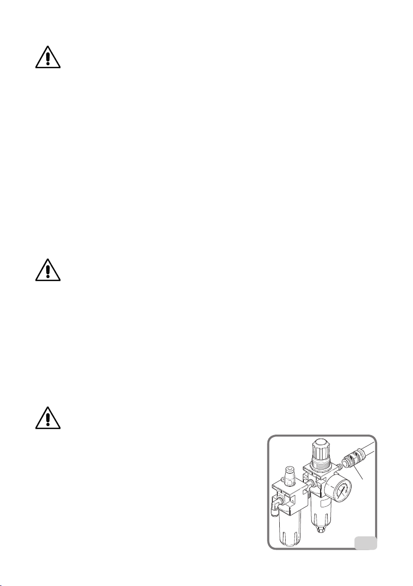
Connect the compressed air system by means of a supply pipe connected to the intake of the air
treatment unit on the REAR SIDE of the machine base.
Check that there is air lubrication oil in the Lubricating unit; rell if there is little or no oil. Use SAE20 oil.
The customer must provide an air cut-off valve upstream of the air treatment and regulating device
supplied with the machine.
WARNING
Connection 1 should be considered as an emergency valve to
disconnect the machine from the air line (g.6)
1
6
Indice
Altri manuali Fasep Smontagomme

Fasep
Fasep BALATRON 331.G3 Manuale utente

Fasep
Fasep RASE.TOP.2248 Manuale utente

Fasep
Fasep TOP AUTOMATIC 4.0 Istruzioni operative

Fasep
Fasep RGU300.ECO Manuale utente

Fasep
Fasep RASE.2234 Manuale utente

Fasep
Fasep V585.2.U Manuale utente

Fasep
Fasep RGU 264 E Istruzioni operative

Fasep
Fasep RGU588E Istruzioni per l'installazione e il funzionamento

Fasep
Fasep BALATRON B433.G3 Manuale utente

Fasep
Fasep V548.G4.U Manuale utente


