FMS EMGZ480 Manuale utente

Operating Manual
EMGZ480
EMGZ480.M16
Digital microprocessor controlled Tension Measuring
Amplifier with integrated CAN-BUS®interface
Operating Manual Version 1.10 10/2007 ff
Firmware Version 1.01
GSD Version 1.00 08/06
This operating manual is also available in German.
Please contact your local representative.
Diese Bedienungsanleitung ist auch in Deutsch erhältlich.
Bitte kontaktieren Sie die Vertretung im zuständigen Land.
© by FMS Force Measuring Systems AG, CH-8154 Oberglatt – All rights reserved.

Operating Manual EMGZ480
2
Table of contents
1Safety Instructions ....................................................................................4
1.1 Warnings 4
1.2 List of Safety Instructions 4
2Definitions..................................................................................................4
3System Components..................................................................................5
4System Description....................................................................................6
4.1 Functional Description 6
4.2 Force Sensor 7
4.3 Electronic Unit EMGZ480, EMGZ480.M16 7
5Quick Installation Guide..........................................................................8
6Dimensions.................................................................................................9
6.1 Dimensions EMGZ480 9
6.2 Dimensions EMGZ480.M16 10
7Installation and Wiring ..........................................................................11
7.1 Mounting the Force Sensors 11
7.2 Mounting the Measuring Amplifier 12
7.3 Connector Configuration and Setting Elements 12
7.4 Wiring Diagrams 14
8Calibrating the Measuring Amplifier ...................................................16
8.1 Simulating Method, Calibration with the PLC or PC 16
8.2 Mathematical Method 17
8.3 Scaling of Analogue Output 18
8.4 Configuring the Lowpass Filter 18
9Parameter Setting....................................................................................19
9.1 List of System Parameters 19
9.2 List of Parameter EMGZ 480 / 480.M16 19
9.3 Description of the System Parameters 20
9.4 Description of Parameters EMGZ480 / 480.M16 21
10 Specification of the CAN-Bus Interface (Devise profile)...................24
10.1 General Remarks 24
10.2 Summary of Objects (application specific) 24
10.3 Device Identification 25
11 CAN Bus Object Catalogue....................................................................26
11.1 Object 2001: Parameter Offset 26
11.2 Object 2002: Parameter Gain 28
11.3 Object 2003: Parameter Force of Sensor 30
11.4 Object 2004: Parameter Unit of Sensor 32
11.5 Object 2005: Parameter Lowpass Filter 34
11.6 Object 2006: Parameter Limit value 1 min or max 36
11.7 Object 2007: Parameter Limit value 1 38
11.8 Object 2008: Parameter Limit value 2 min or max 40
11.9 Object 2009: Parameter Limit value 2 42

Operating Manual EMGZ480
3
11.10 Object 2040: Parameter scaling analogue output 44
11.11 Object 2051: Parameter Find offset 46
11.12 Object 2052: Parameter Calibration 47
12 CAN-BUS Catalogue System Parameter Objects................................48
12.1 Object 2080: System Parameter Language 48
12.2 Object 2081: System Parameter Measuring System 50
12.3 Object 2082: System Parameter Baudrate 52
12.4 Object 2083: System Parameter Cycle time PDO 54
13 CAN-BUS Catalogue Operating System Objects.................................56
13.1 Object 7100: Cross values A/D-Converter 56
13.2 Object 7130: Feedback value 57
14 CAN-BUS Catalogue Action Objects....................................................58
14.1 Object 2210h: Parameter Set Default Parameters 58
15 CAN-BUS Catalogue Status Objects.....................................................59
15.1 Object 2100: Operating status 59
15.2 Object 6150: Analogue Input Status 60
15.3 Object 6508: Alarms 61
16 Communication Profile...........................................................................62
16.1 PDO_0 (1800 / 1A00) ID: 180h + Node ID 62
16.2 PDO_1 (1801 / 1A01) ID: 280h + Node ID 62
17 Complete Object Overview ....................................................................63
18 Non-Volatile Data Memory (EEPROM)...............................................64
19 Technical Reference................................................................................65
19.1 Other Elements for Settings of EMGZ 480 65
19.2 Function of the CAN-Bus LED (red) 65
20 Trouble Shooting.....................................................................................66
21 Technical Data.........................................................................................67
Operating Manual EMGZ480
4
1Safety Instructions
1.1 Warnings
a) High danger of health injury or loss of life
Danger
This symbol refers to high risk for persons to get health injury or loss life. Instructions
have to be followed strictly.
b) Risk of damage of machines
Caution
This symbol refers to information, that, if ignored, could cause heavy mecanical damage.
This warning has to be followed absolutely.
c) Note for proper function
Note
This symbol refers to important information about proper use of the devise. If not
followed, malfunction can be the result.
1.2 List of Safety Instructions
The functionality of the Tension Measuring Amplifier is only guaranteed, if the
components and their application are used as recommended by FMS. Arrangements
other than the one recommended here can cause heavy malfunction. The installation
instructions on the following pages must strictly be followed.
Local installation regulations are to preserve safety of electric equipment. They are not
taken into consideration by this operating manual. However, they have to be strictly
followed.
Improper handling may damage the fragile electronic equipment! Don’t use rough
tools such as screwdrivers or pliers! Operators handling the processor board must
wear a well earthed bracelet in order to discharge static electricity.
Bad earth ground connection may cause electric shock to persons, malfunction of the total
system or damage of the electronic unit! It is vital to ensure that proper ground connection is
done.

Operating Manual EMGZ480
5
2Definitions
CAN (Controller Area Network): CAN is an asynchronous, serial bus system. It was
designed to reduce wires in cable harnesses. The CAN bus system works according the
Carrier Sense Multiple Access / Collision Avoidance System. It’s a very reliable system that
is used in large numbers in the automotive industry since 1989.
Offset: Correction value for compensation of the roller or pulley weight. The offset
adjustment ensured that a force of 0N will generate a signal of 0V exactly.
Gain: Amplification factor for the measuring signal. The proper value will set the
measuring range of the sensor to the corresponding output range of the signal.
3System Components
An EMGZ480/EMGZ480.M16 system consist of the following components (refer to Fig. 1
and Fig. 2):
Force sensors
•For mechanical/electrical conversion of the tension force
•Force measuring bearing
•Force measuring roller
•Force measuring journal
Electronic unit EMGZ480
•Supplying 1 or 2 force sensors
•With integrated CAN-BUS interface for operation and parametrisation
•Operates as CAN Open CiA-DS 301 Slave
•One analogue output
•Wall mounting version
Electronic unit EMGZ480.M16
•Optimised for rotating applications (M16 connector)
•Supplying 1 or 2 force sensors
•With integrated CAN-BUS interface for operation and parametrisation
•Operates as CAN Open CiA-DS 301 Slave
•Wall mounting version
CAN-BUS master computer
•For operation of the electronic unit EMGZ480 / EMGZ480.M16
•Operates as CAN Open CiA-DS 301 Master
•Any master computer or PLC suitable
(Italic text indicates a variant or option)
Operating Manual EMGZ480
6
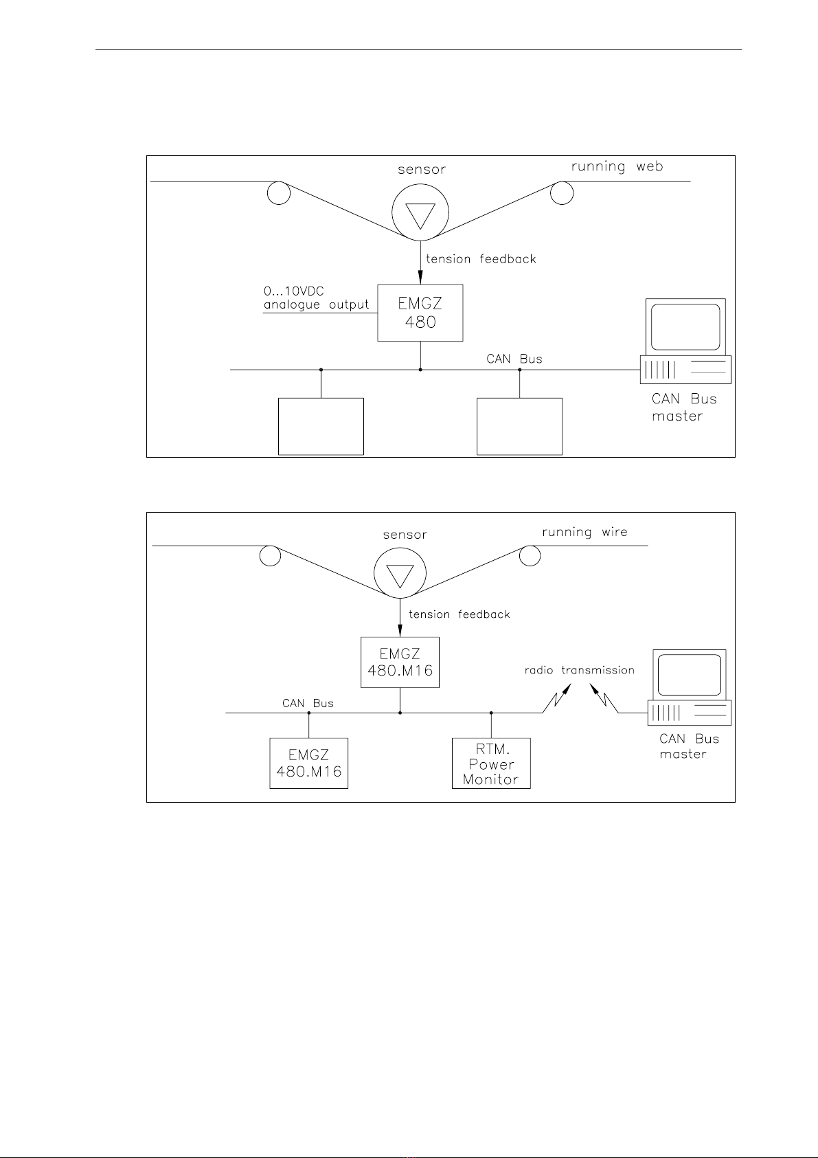
4System Description
Fig. 1: Basic application of the EMGZ480 Tension Measuring Amplifier E480001e
Fig. 2: Basic application of the EMGZ480.M16 Tension Measuring E480015e
Amplifier with wireless data transmission
4.1 Functional Description
The force measuring sensor gathers the tension force in the material and transmits the
value as a mV signal to the electronic unit. There the mV signal is amplified and
conditioned depending on the chosen configuration. The resulting feedback value can be
read by the CAN-BUS master. The application dependent calculations are done by the
CAN-BUS master.
Operating Manual EMGZ480
7
4.2 Force Sensor
The force measuring sensors base on the flexion or dual flexion beam principle. The
flexion in the sensor body is measured by strain gauges as a mV signal. In order to
minimize the power supply influence to the strain gauges Wheatstone Bridge and achieve
a clean and accurate amplification, the force sensors are supplied with a very stable,
controlled supply voltage.
4.3 Electronic Unit EMGZ480, EMGZ480.M16
General Information
A microprocessor in the electronic unit handles all calculation and communication tasks.
The electronic unit contains a signal amplifier with a highly accurate sensor power supply
section. The integrated CAN-BUS interface block handles the CAN-Bus protocol.
EMGZ480 and EMGZ480.M16 can process the signals of two force sensors (sum signal).
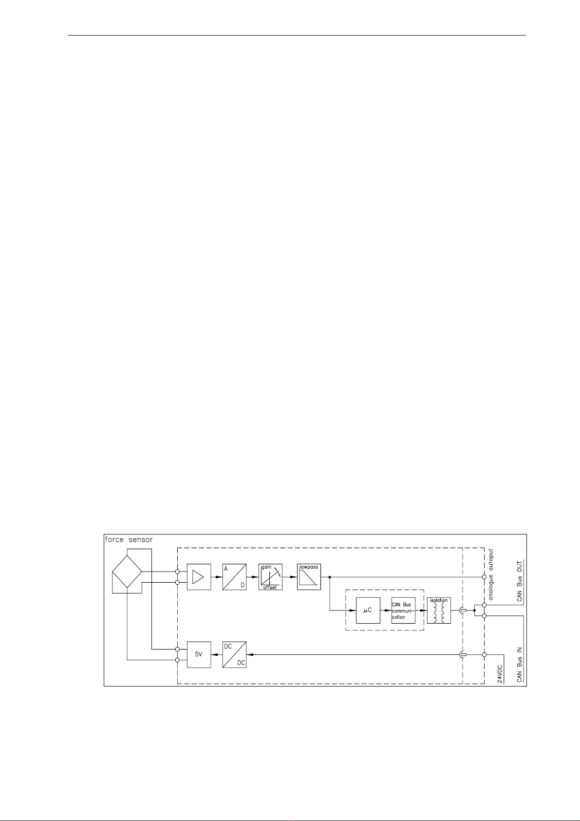
Strain Gauge Amplifier
The strain gauge amplifier section provides the highly accurate 5V DC supply voltage for
one or two force measuring sensors. A highly accurate, fixed difference amplifier raises
the mV signal to the Volt-range (up to10V). This signal is fed to 14-Bit A/D converter.
The microprocessor conditions the signal and calculates all application specific
parameters like Offset, Gain, Filter and Limit values. The digitalised signal can then be
read by the CAN-BUS master.
CAN-BUS Interface
The EMGZ480 and EMGZ480.M16 operate the CAN Open / CiA-DS 301 interface. The
interface is galvanically isolated.
Operation
The entire parameter setting is done over the CAN-BUS. Parameters and settings are
stored in a none-volatile memory, completely fail-save
Fig. 3: Block Diagram EMGZ480 E480005e

Operating Manual EMGZ480
8
5Quick Installation Guide
•Collect and check all your requirements such as: Configuration of the CAN-BUS
interface (address number, data format, Baudrate, PDO cycle time, termination, etc),
calibration mode (ref. to „8. Calibrating the measuring amplifier“).
•Draw your final wiring diagram according to FMS recommendations (refer to „7.
Installation and wiring“)
•Install and wire all your components (refer to „7. 4Installation and wiring“)
•Set your parameters in the CAN-BUS master computer (ref. to „10. Specification of
the CAN-BUS interface“)
•Put EMGZ480 measuring amplifier into operation and calibrate it by means of CA-
BUS (refer to „8. Calibrating the measuring amplifier“)
•Turn system on and proceed with a test run with low speed
•If required, activate additional application-specific functions of the CAN-BUS master
computer (DP master)
Note
If a real-time control loop is implemented with the CAN-BUS, you must ensure that the
application-specific CAN-BUS protocol is time wise short enough to provide sufficient
control dynamics.
Operating Manual EMGZ480
9
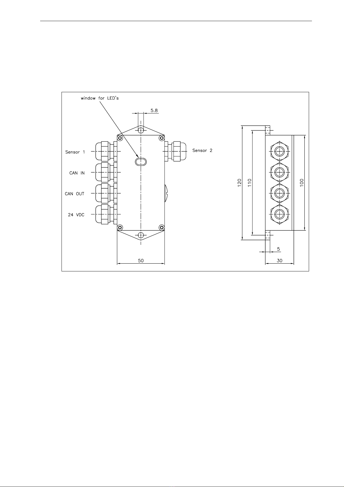
6Dimensions
6.1 Dimensions EMGZ480
Fig. 4: Outline drawing EMGZ480 C480017e
Operating Manual EMGZ480
10
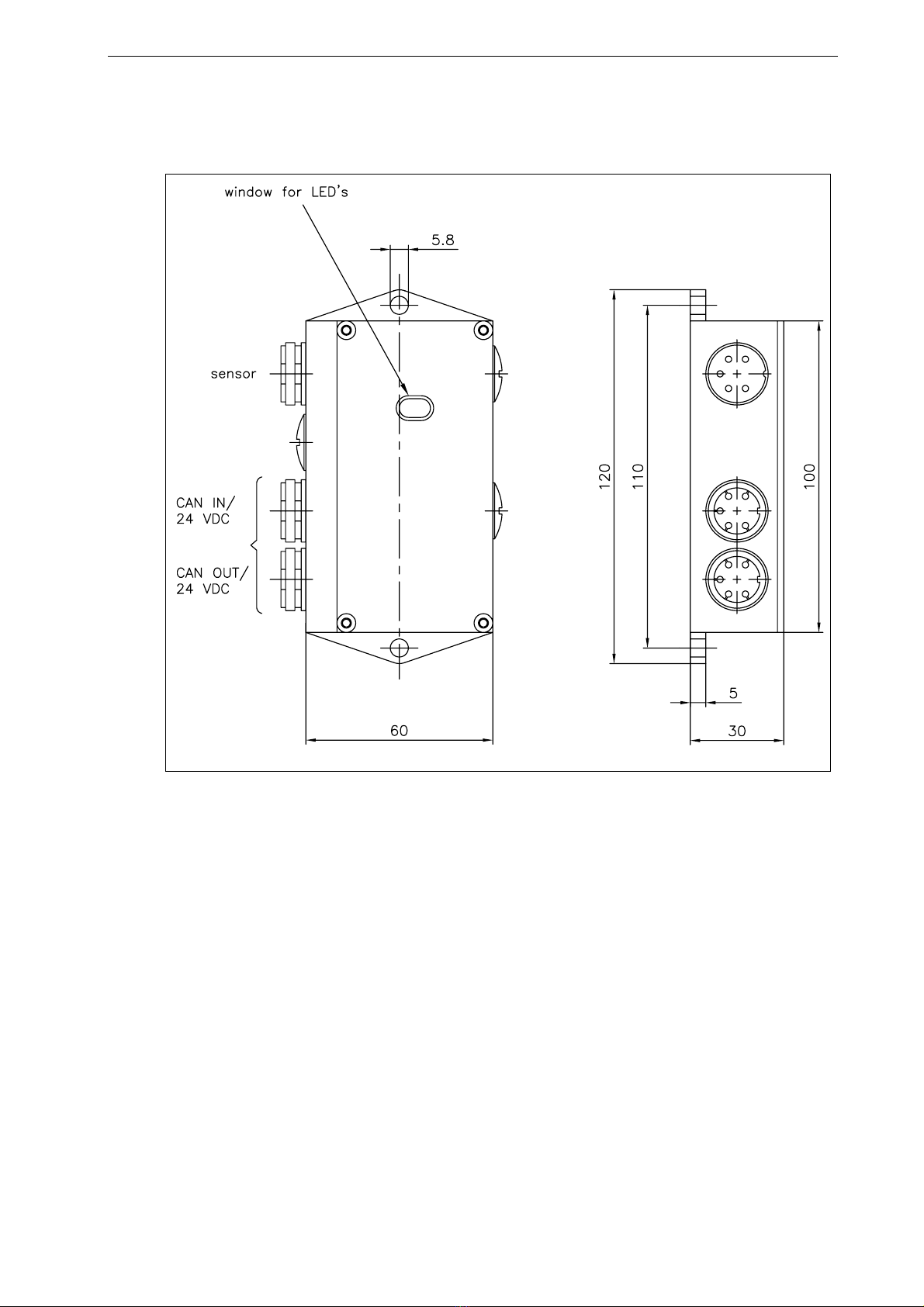
6.2 Dimensions EMGZ480.M16
Fig. 5: Outline drawing EMGZ480.M16 C480018e
EMGZ480 and EMGZ480.M16 come in robust and resilient aluminium housing. They
were designed to work under the most stringent environmental conditions. The sealed
housing is rated for a protection class of IP68.
Questo manuale è adatto per i seguenti modelli
1
Indice
Altri manuali FMS Strumento di misura


