
FRC SeatMonitor SBA1GD Manuale utente
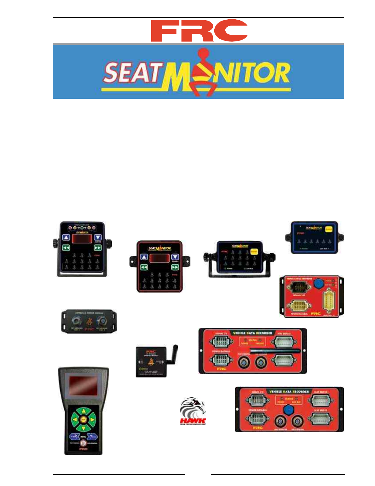
SBA1HM Rev120113
1
FIRE RESEARCH CORPORATION
www.reresearch.com
26 Southern Blvd., Nesconset, NY 11767
TEL 631.724.8888 FAX 631.360.9727 TOLL FREE 1.800.645.0074
Document Number:
XE-SBA1PMHM-R0A
SBA100
SBA300
SBA400
SBA200
Proprietary
Software
SEAT MONITOR AND
DATA ACQUISITION SYSTEM
HARDWARE MANUAL
The SBA document set includes the following:
SBA1GD General Description
SBA1HM Hardware Manual
SBA1UG User Guide
SBA2DC Data Collector Manual
SBA2EM OEM Guide
Vehicle Data
Recorders
Lateral G Sensor
Data
Collector
12-Seat Wireless
12-Seat USB
6-Seat USB
Wireless
Interface

SBA1HM Rev120113
2
CONTENTS
Table of Contents
CONTENTS ................................................................................................................ 2
INTRODUCTION ...................................................................................................... 4
Overview ................................................................................................................ 4
Features .................................................................................................................. 5
Specications ......................................................................................................... 6
SYSTEM DESCRIPTION .......................................................................................... 8
Components ........................................................................................................... 8
System Layout ..................................................................................................... 10
Display Module Controls and Indicators ............................................................. 12
Vehicle Data Recorder ......................................................................................... 14
Wireless Communications ................................................................................... 16
Data Collector ...................................................................................................... 16
Wireless Interface Module ................................................................................... 16
WatchDog PRO Module ...................................................................................... 17
INSTALLATION ...................................................................................................... 18
Install Seat Monitor Display Module................................................................... 18
Install 12-Seat Vehicle Data Recorder ................................................................. 20
Install 6-Seat Vehicle Data Recorder ................................................................... 22
Install Lateral G Sensor Module .......................................................................... 23
Data Collector ...................................................................................................... 24
Wireless Interface ................................................................................................ 25
SYSTEM POWER .................................................................................................... 26
SEAT MONITOR DISPLAY OPERATION ............................................................. 28
Message Display (SBA100, SBA200) ................................................................. 28
Set the Time (SBA100, SBA200) ........................................................................ 29
Set the Lateral G Indicator (SBA100) ................................................................. 29
Self-Test Mode ..................................................................................................... 30
Operational Check ............................................................................................... 31
WIRING .................................................................................................................... 32
Cables .................................................................................................................. 32
12-Seat Vehicle Data Recorder Connectors ......................................................... 34
6-Seat Vehicle Data Recorder Connectors ........................................................... 36
Vehicle Data Recorder Harness Connections ...................................................... 37
Seat Monitor Display Harness Connections ........................................................ 38
Ford Vehicle Data Recorder and Harness Connections ....................................... 39
Lateral G Sensor Module Harness Connections .................................................. 40
WatchDog PRO Modules ..................................................................................... 41

SBA1HM Rev120113
3
List of Tables
Table HM-1. System Power ....................................................................................... 7
Table HM-2. Display Module Message Display ...................................................... 28
Table HM-3. SBA100, SBA200 Self-Test Mode ..................................................... 30
List of Figures
Figure HM-1. General Layout, 12-Seat System ...................................................... 10
Figure HM-2. General Layout, 6-Seat System and WatchDog PRO ....................... 11
Figure HM-3. Wireless Communications ................................................................ 16
Figure HM-4. SBA300/400 Display Module U-Bracket Mount ............................. 18
Figure HM-5. SBA300/400 Display Module Surface Mount .................................. 19
Figure HM-6. SBA100/200 Display Module U-Bracket Mount ............................. 19
Figure HM-7. SBA100/200 Display Module Surface Mount .................................. 19
Figure HM-4. SBA300/400 Display Module U-Bracket Mount ............................. 18
Figure HM-5. SBA300/400 Display Module Surface Mount .................................. 19
Figure HM-6. SBA100/200 Display Module U-Bracket Mount ............................. 19
Figure HM-7. SBA100/200 Display Module Surface Mount .................................. 19
Figure HM-8. 12-Seat VDR Mounting Dimensions ................................................ 21
Figure HM-9. 6-Seat VDR Mounting Dimensions .................................................. 22
Figure HM-10. Lateral G Sensor Module Mounting Dimensions ........................... 23
Figure HM-11. Data Collector Dimensions ............................................................. 24
Figure HM-12. Computer Wireless Interface Dimensions ...................................... 25
Figure W-1. Cables .................................................................................................. 32
Figure W-2. 12-Seat VDR Connectors .................................................................... 34
Figure W-3. 6-Seat VDR Connectors ...................................................................... 36
Figure W-4. VDR Harness Connections .................................................................. 37
Figure W-5. Seat Monitor Display Harness Connections ........................................ 38
Figure W-6. Ford VDR and Harness Connections ................................................... 39
Figure W-7. Lateral G Sensor Module Connections ................................................ 40
Figure W-8. WatchDog PRO Module Connections ................................................. 41
Glossary of Terms
Pairing
Note: A VDR shall not be paired until the vehicle is delivered and the pairing process is carried out using
the end users copy of HAWK software.
This process establishes a permanent association between the copy of HAWK software that is loaded on the end
users computer and the vehicle VDR. Stored data from the VDR can only be uploaded and saved to this copy of HAWK
software.
Paired Vehicle VDR
The VDR is secured so that the program and stored data is only accessible by personnel authorized by the end user.
A paired VDR has the vehicle name, vehicle identication number, and the end users password embedded into its memory.
Unpaired Vehicle VDR
A new VDR that has not been associated with a copy of HAWK software. An unpaired VDR can be accessed using
HAWK OEM software to upload programming.

SBA1HM Rev120113
4
INTRODUCTION
This Hardware Manual includes the information needed to install the Seat
Monitor and Data Acquisition System vehicle mounted hardware. It includes hardware
specications, mounting instructions, power-up information, and wiring diagrams.
Refer to the General Description (SBA1GD) for overall system information; the
Hardware Manual (SBA1HM) for hardware specications, mounting instructions, and
wiring; the User Guide (SBA1UG) for HAWK software installation, set-up, and how to
instructions for the data management software; the Data Collector Manual (SBA2DC)
for instructions on using the FRC portable data collector; the OEM Guide (SBA2EM)
for information needed by body builders, dealers, and service personnel to use the body
builder/service programs in HAWK.
Overview
The Seat Monitor and Data Acquisition System is available with four different
Seat Monitor Display modules. The simplest model has six seat belt icons and a silence
button for the audible alarm. More complex models will include a message display,
push buttons for navigating through programs, vehicle system warning indicators, and
the lateral acceleration indicator.
The Vehicle Data Recorder (VDR) houses the on-board computer and software,
the hardware for all system interconnections, and the wireless or USB interface. It is
capable of processing input data from the vehicle J1939 CAN Bus, the data link, or
separate hard-wired inputs. The VDR communicates via the proprietary FRC datalink
with the system modules.
The Seat Monitor and Data Acquisition System consist of the following components:
Seat Monitor Display Module
Vehicle Data Recorder (VDR)
Lateral G Sensor Module (SBA100 Models Only)
Datalink Terminating Resistor
Cables
Wireless Interface Module
Data Collector
HAWK Data Management Software
The Data Collector, the Wireless Interface Module, and the HAWK Software are not
mounted on the vehicle. All communications between the wireless VDR and the Data
Collector or a computer are accomplished via wireless technology. All communications
between a VDR with the USB interface and a computer are accomplished via a USB
cable.

SBA1HM Rev120113
5
Features
The Seat Monitor and Data Acquisition System has been designed with the
following unique features:
Exceeds NFPA 1901 Standard for Automotive Fire Apparatus 2009 Edition,
paragraph 4.11 requirements for a Vehicle Data Recorder.
48 Hours of Stored Second-by-Second Data
100 Engine Hours of Stored Minute-by-Minute Summary Data
All Data is Date and Time Stamped
All Stored and Collected Data is Password Protected
HAWK Data Management Software Package
J1939 CAN Bus Interface
Discrete Inputs (When Data is not Available on J1939 CAN Bus)
Wireless Interface for Uploading Data from 12-Seat VDR
Data Collector Remotely Uploads and Stores Data from 12 VDRs
USB Port for Uploading Data from 6-Seat VDR
Exceeds NFPA 1901 Standard for Automotive Fire Apparatus 2009 Edition,
paragraph 14.1.3.10 requirements for a Seat Belt Warning system.
Monitors up to 13 Seating Positions
Provides a Visual Display Showing the Condition at Each Position
Validates Sit and Buckle Sequence
Audio and Visual Alarm Outputs
Highly Visible LED Display
Programmable Seat Conguration
Lateral G Indicator

SBA1HM Rev120113
6
Specications
Power is connected to the Vehicle Data Recorder (VDR) and then supplied to the
system modules via the 5-Pin Seat Monitor cable or FRC harness connectors.
System Power
The VDR Supply Power input (POWER/DATABUS connector pins 1 and 2) is
directly connected to battery power. (A 10 AMP fuse between pin 1 and the battery is
recommended.) When there is no activity on the VDR and the vehicle ignition is off
the system goes into the sleep mode.
Power to each module in the Seat Monitor and Vehicle Data Acquisition System
is provided through the VDR via the 5-Pin cable(s) or wiring. Power requirements for
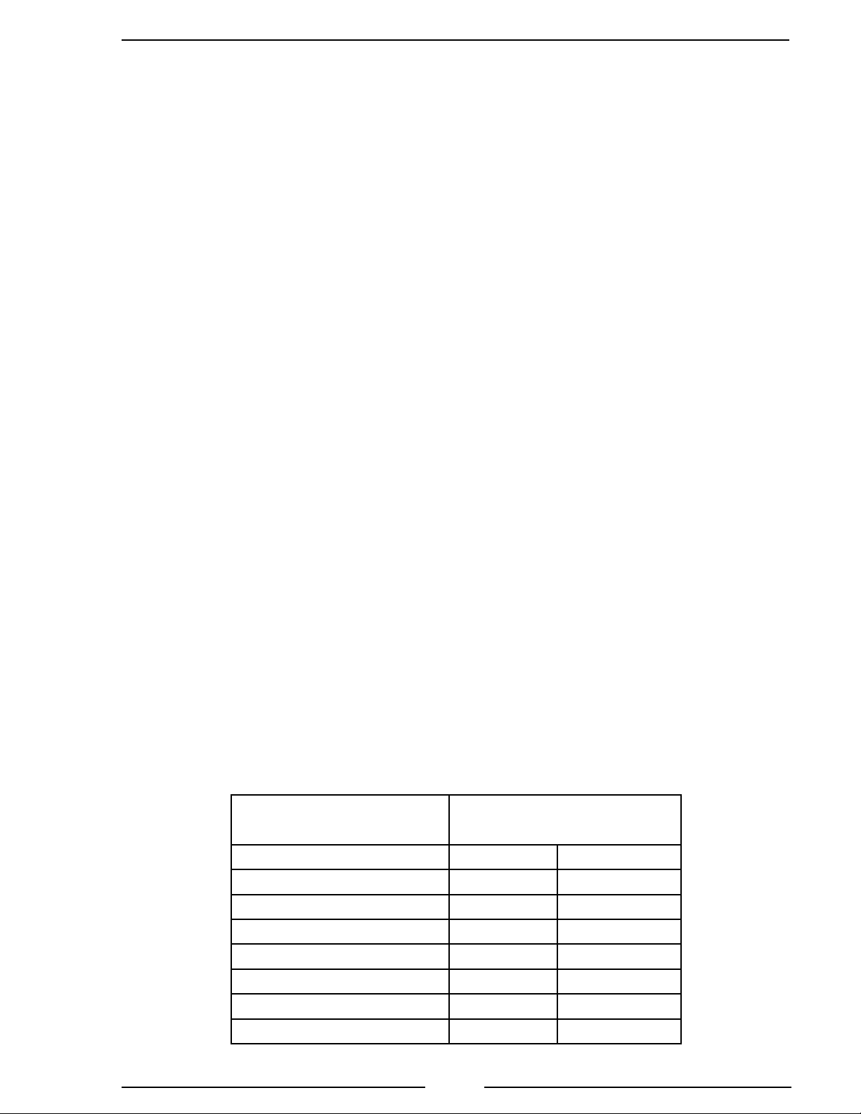
these modules are shown in Table HM-1 System Power. The total system supply current
required (pins 1 and 2 of the VDR POWER DATA/BUS connector) is the sum of the
requirements of all the modules installed.
Seat Monitor Display Module
Supply Voltage: 9 - 30 VDC (Over 5-Pin Cable or VDR Harness)
Dimensions:
SBA100 4" W 4 1/2" H 1 7/16" D
SBA200 4" W 4 1/2" H 1 7/16" D
SBA300 5 1/8" W 2 7/8" H 1 5/16" D
SBA400 5 1/8" W 2 7/8" H 1 5/16" D
*Dimensions do not include the mounting bracket.
Vehicle Data Recorder
The wireless device complies with the Code of Federal Regulations, Title 47, Part 15, FCC
Rules and Regulations.
Supply Voltage: 9 - 30 VDC
Supply Current: Refer to Table HM-1 System Power
12-Seat Dimensions: 9 7/8" by 3 3/4" by 2 1/2" *
* This is 5 5/8" with antenna extended.
6-Seat Dimensions: 5 7/8" by 3 3/4" by 1 7/8"
Lateral G Sensor Module Option
Supply Voltage: 9 - 30 VDC (From VDR Over 5-Pin Cable)
Supply Current: Refer to Table HM-1 System Power
Dimensions: 5" by 2" by 1 3/4"
SBA1HM Rev120113
7
Table HM-1. System Power
Module Supply Current (in Amps)
12 VDC 24 VDC
SBA100 Display 1.0 0.5
SBA200 Display 1.0 0.5
SBA300 Display 0.7 0.35
SBA400 Display 0.7 0.35
12-Seat VDR Module 0.2 0.1
6-Seat VDR Module 0.2 0.1
Lateral G Sensor Module 0.2 0.1
WatchDog PRO 0.08 0.04
Data Collector
Supply Power:
Portable Operation 9 VDC Lithium Battery
USB Port Connected USB Cable
Dimensions: 4 1/2" by 7 3/4" by 1 1/4"
Wireless Interface
This device complies with the Code of Federal Regulations, Title 47, Part 15, FCC Rules and
Regulations.
Supply Power: USB Cable (Connected to Computer)
Dimensions: 2 5/8" by 2 5/8" by 1 1/8" *
* This is 4" with the antenna raised.
Watch Dog PRO
Supply Voltage: 9 - 30 VDC
Inputs: 8 or 18, Active Low
Dimensions: 5 7/8" by 3 3/4" by 1 7/8"
Note: Other products may have inputs into the FRC VDR. Refer to the specic
product manual for installation information.

SBA1HM Rev120113
8
SYSTEM DESCRIPTION
Refer to the General Description (SBA1GD) for more detailed system information
or the User Guide (SBA1UG) for HAWK Software details.
Components
The Seat Monitor and Data Acquisition System consist of the following components:
Seat Monitor Display Module
Vehicle Data Recorder
Data Collector (Wireless VDR Only)
Wireless Interface Module (Wireless VDR Only)
Hawk Data Management Software Package
Lateral G Sensor Module (SBA100 Models Only)
WatchDog PRO Module (Optional)
Datalink Terminating Resistor
Cables
Note: Other components may have inputs into the FRC VDR. Refer to the
specic product manual for information.
Seat Monitor Display Module
This module is mounted in the cab. It provides a visual display for the driver or
ofcer showing the condition of each seating position along with parking brake engaged
and door open warning icons. The data that the VDR is recording can be viewed live
on display models that include a message display.
Vehicle Data Recorder (VDR)
The VDR monitors vehicle data via the J1939 CAN Bus and wired inputs. The data
is collected, stored, and available to be uploaded to a computer running HAWK data
management software. The VDR communicates with HAWK software via a Wireless
Interface, wireless Data Collector or some models use a connected USB cable.
Data Collector, Wireless Interface Module, and Hawk Data Management
Software Package
These components are not mounted on the vehicle. Reference in this publication to
these three components are informative and given to aid in the overall understanding
of the complete system.

SBA1HM Rev120113
9
Lateral G Sensor Module (SBA100 Models Only)
Provides the input for the LATERAL G INDICATOR on the SBA100 display
module. The lateral G indicator provides a visual cue to the driver and ofcer of the
side forces on the vehicle as it is cornering or being operated on a slope.
WatchDog PRO Module
The WatchDog PRO installs as an integral part of the Seat Monitor and Data
Acquisition System to provide an output if the vehicle is moved when a hazardous
condition exists. It monitors the condition of any device permanently attached to the
apparatus that may be open, extended, or deployed in a manner that is likely to cause
damage to the apparatus or device if the apparatus is moved.
SBA1HM Rev120113
10
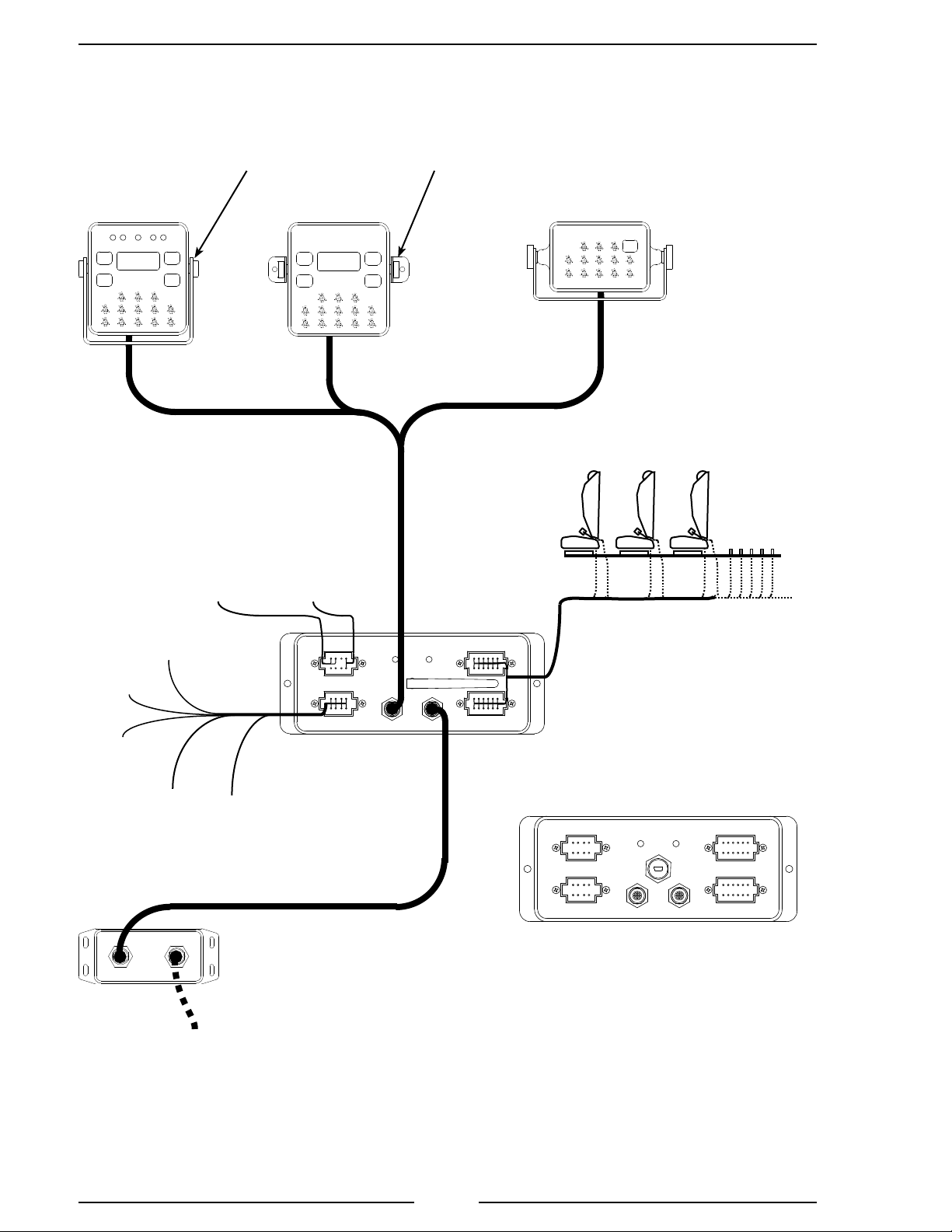
Figure HM-1. General Layout, 12-Seat System
SBA300
SBA200
SBA100
5-Pin Seat
Monitor
Cable To Seat Belt and
Seat Switches
12-Seat
VDR Module
5-Pin FRC
Datalink
Cable
Alarm
Outputs FRC
Datalink
Supply
Power
Ignition
Switch
J1939
CAN
Master
Optical
Warning
Parking
Brake
Interlock
The Seat Monitor display modules are
available with two mounting options.
The SBA100 requires that the
Lateral G Sensor Module is
installed. It provides the input
to the Lateral G Indicator. The
SBA200 and SBA300 do not
require this module.
U-Bracket
Mount Surface
Mount
System Layout
Refer to Wiring Section for
detailed information on pinouts,
cables, and connectors.
Wireless
Interface
USB
Interface
Future expansion. When there is
no cable connected here, the FRC
Datalink Terminating Resistor must
be installed. When the Lateral G
Sensor Module is not installed, the
terminating resistor must be installed
on the VDR FRC Datalink connector.
Wiring is the same for both 12-Seat VDRs.
SBA100 Only
When multiple display
modules are used, the
terminating resistor at the
module with the tee tting
needs to be unterminated.
Lateral G
Sensor Module
Monitors up
to 12 Seat
Belt and Seat
Switch Inputs
Questo manuale è adatto per i seguenti modelli
4
Indice
Altri manuali FRC Strumento di misura

FRC
FRC Air Sentinel AMA200 Manuale utente

FRC
FRC DFA400 Manuale utente

FRC
FRC FPA400 Manuale utente

FRC
FRC FPA400 Manuale utente

FRC
FRC Insight Ultimate Series Manuale utente

FRC
FRC ThrottleXcel ELA100 Manuale utente

FRC
FRC DATATRON FTC200 Manuale utente

FRC
FRC Insight Series Manuale utente

FRC
FRC ThrottleXcel ELA100 Manuale utente

FRC
FRC DFA400 Manuale utente


