FS S5860 Series Manuale operativo
Innovation · Expertise · Agility
S5860 Series
Switches Hardware Installation
and Maintenance Guide
V1 .0 .2306A

Audience:
This document is for network engineers responsible for installing
and maintaining S5860 series switches. Experience with network
equipment installation and maintenance is required.
Feature Statement:
Please visit the FS.COM Technical Documents page to download the
datasheet and obtain information on the specifications supported
by the product .
Safety Statement:
•To avoid harm to people and equipment, please read the safety
recommendations in the Safety Precautions for FS Switches
before installing the FS Switch .
•Verify that the requirements described in the Safety Precautions
for FS Switches have been met .
Innovation · Expertise · Agility 1
Preface

1. Hardware Installation and Parts Replacement
Contents
Innovation · Expertise · Agility 2
1.1 Installation Procedure
1.2 Installation Preparation
1.3 Installing a Switch
1.4 Installing Modules
1.5 Connecting a Switch
1.6 Post-Installation Checks
1.7 System Commissioning
1.8 Parts Replacement
04
04
06
08
11
14
15
18
2. Troubleshooting After Installation
2.1 Troubleshooting Flowchart
2.2 Guide to Using Switches
2.3 Guide to Using Optical Modules
24
25
27

Hardware Installation
and Parts Replacement
Innovation · Expertise · Agility 3
The S5860 series switches, launched by FS.com, are a new generation of Layer 3
switches that integrate high performance, high security, and multiple services. They
are primarily used in the convergence layer of campus networks, providing line-speed
multi-layer switching and comprehensive QoS (Quality of Service) policies. They
classify and prioritize different types of traffic based on specific applications, ensuring
minimal latency for critical data transmission.

Item
Requirement
Cleanliness
The device must be installed in a clean, dry, and well ventilated standard equipment room with controllable
temperature .
Dust proofing
Dustproof measures must be taken in the site . Dust will cause electrostatic discharges on the chassis and
affect connections of metal connectors and joints . This shortens service life of the device and may cause
failures of the device .
Temperature and
humidity
The equipment room must be free from leaking or dripping water, heavy dew, and damp . The temperature
and humidity in the installation site must be within specifications . For the operating temperature and
relative humidity ranges required by the device, see the device specifications . If the relative humidity
exceeds 70%, using dehumidifiers or dehumidifying air conditioners is recommended .
Corrosive gases
avoidance
The installation site must be free from acidic, alkaline, or corrosive gases.
Hardware Installation and Parts Replacement
Switch Hardware Installation and Maintenance Guide
1.2 Installation Preparation
The S5860 series switches are relatively complex devices. Before installation, careful planning and
arrangements should be made for the installation location, networking mode, power supply and wiring of the
devices. Confirm the following before installation:
1.2.1 Checking the Installation Site
Innovation · Expertise · Agility 4
1.1 Installation Procedure
Installing Modules
Installation Preparation Installing a Switch
Post- Installation Checks
System Commissioning Connecting a Switch
End
•The installation site provides sufficient space for heat dissipation.
•The installation site meets the temperature and humidity requirements of the switch.
•The power supply and required current are available on the installation site.
•The Ethernet cables have been deployed on the installation site.
The S5860 series switches must be installed indoors.The installation site must meet the following
requirements.
Table 1: Requirements for the Installation Site

Innovation · Expertise · Agility 5
1.2.2 Mounting the Cabinet or Rack
Precautions
•All expansion bolts for fastening the cabinet base to the ground should be installed and tightened in
sequence from bottom to up (large flat washer, spring washer, and nut), and the installation holes on the
base and the expansion bolts are aligned.
•The installed cabinet is not movable after installation.
•The installed cabinet is vertical to the ground.
•When multiple cabinets are placed side by side in the equipment room, they should be aligned with each
other, leaving an error less than 5mm (0.20 in.).
•The front and rear doors of the cabinet should be installed to allow you open and close them smoothly. The
locks should work normally, and all keys should be complete.
•There should be no unnecessary and informal labels inside the cabinet and on service modules.
•Filler panels are installed in empty slots.
•The switch is securely installed, and the screws on the panel should be fastened tightly.
•All wiring outlets at the top and bottom of the cabinet should be installed with rodent-resistant nets with
openings of no more than 15mm (0.59 in.) in diameter to prevent rodents and other small animals from
entering the cabinet.
• An anti-static wrist strap should be provided in the cabinet. The screws in the cabinet should be fastened
tightly and be of the same model.
1.2.3 Checking the Power Conditions
When mounting the cabinet, please note the following:
Installation Steps
1. Plan the available space before installing the cabinet. Maintain a clearance before the front and back doors
for maintenance and operation.
2. Install and fasten the cabinet in the specified site as planned.
3. Install the cable troughs and cables.
4. Install the trays and cable management brackets on the rack according to the number of switches installed
into the cabinet.
Hardware Installation and Parts Replacement
Switch Hardware Installation and Maintenance Guide
•Before use, please check whether there is obvious damage to the power supply shell and whether the
power supply is defective, such as abnormal noise.
•The device is only allowed to be plugged into the power module that accompanies the device, otherwise it
may lead to unknown risks.
•Power module in 1+1 backup can be hot-swapped one of them, need to ensure that the other power module
on the equipment is in the power supply state when replaced, otherwise unplugging the power module will
cause the switch to lose power, resulting in business interruption.
• Prohibit the mixed use of power modules with different power and different cooling methods.

Innovation · Expertise · Agility 6
Before installing the S5860 series switch in a cabinet, please check whether the racks are properly positioned.
If the racks are too closeto the front door of the cabinet, you may not be able to close the front door after
plugging in the Ethernet and fiber cables .The front panel of the switch should be at least 10 mm (0.39 in.)
away from the front door of the cabinet. Please confirm the following before installing the switch:
1.2.4 Preparing Installation Tools and Accessories
1.3.1 Mounting the Switch in a Cabinet or Rack
•The cabinet is secured.
•The modules in the cabinet are installed.
•There are no obstructions in and around the cabinet.
•The switch is prepared and transported to a location close to the cabinet.
Common Tools
Phillips screwdriver, Ethernet and optical cables, cage nuts, diagonal pliers and cable ties
Special Tools
Anti-static gloves, wire stripper, crimping plier, RJ45 connector crimping plier, and wire cutter
Cleaning Tools
Dust-free paper and fiber end-face microscope
Meters
Multimeter, bit error rate tester (BERT), and optical power meter
•The S5860 series switches are delivered without a tool kit. Please prepare a tool kit.
1.3 Installing a Switch
Precautions
Mounting the Brackets
1. 1. Take out the two L-shaped mounting brackets and the M4*8FMO flat head screws from the plastic bag.
2. Place the mounting brackets against the side walls of the switch and secure them using the M4*8FMO
flathead screws. The installation method is the same for both sides.
Figure 1: Mounting the Brackets
Hardware Installation and Parts Replacement
Switch Hardware Installation and Maintenance Guide
Innovation · Expertise · Agility 7
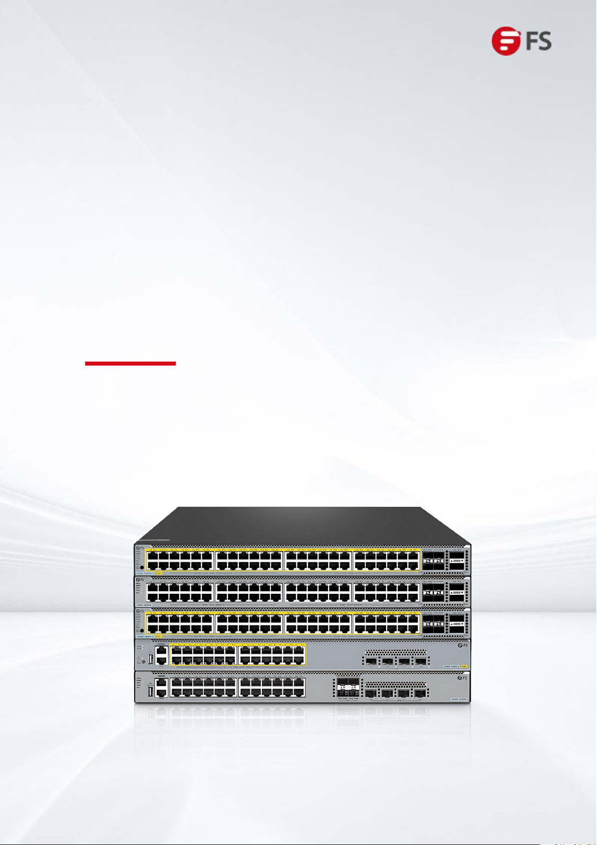
1.3.1 Mounting the Switch in a Cabinet or Rack
Mounting the Switch in a Rack
The S5860 series switches are designed to meet the EIA standard size and can be installed in a 19-inch rack.
During installation, the front panel of the switch should be placed forward on the brackets. It is recommended
to use a tray for mounting the S5860 series switch and then secure it to the rack brackets. Alternatively, the
provided rear brackets can be used for fixation. The S5860 series switches have a smaller depth and do not
come with rear brackets as standard equipment.
Figure 2: Mounting the Switch in a Rack
•The mounting position for wall-mount installation is the four screw holes on the left and right sides of the
rear panel of the main unit.
•Differentiate the left and right rear brackets based on the direction indicated on the brackets.
•The provided rear brackets are only suitable for cabinets with a depth of 800 mm-1200 mm.
Hardware Installation and Parts Replacement
Switch Hardware Installation and Maintenance Guide
Innovation · Expertise · Agility 8
1.4.1 Installing of Fan Modules
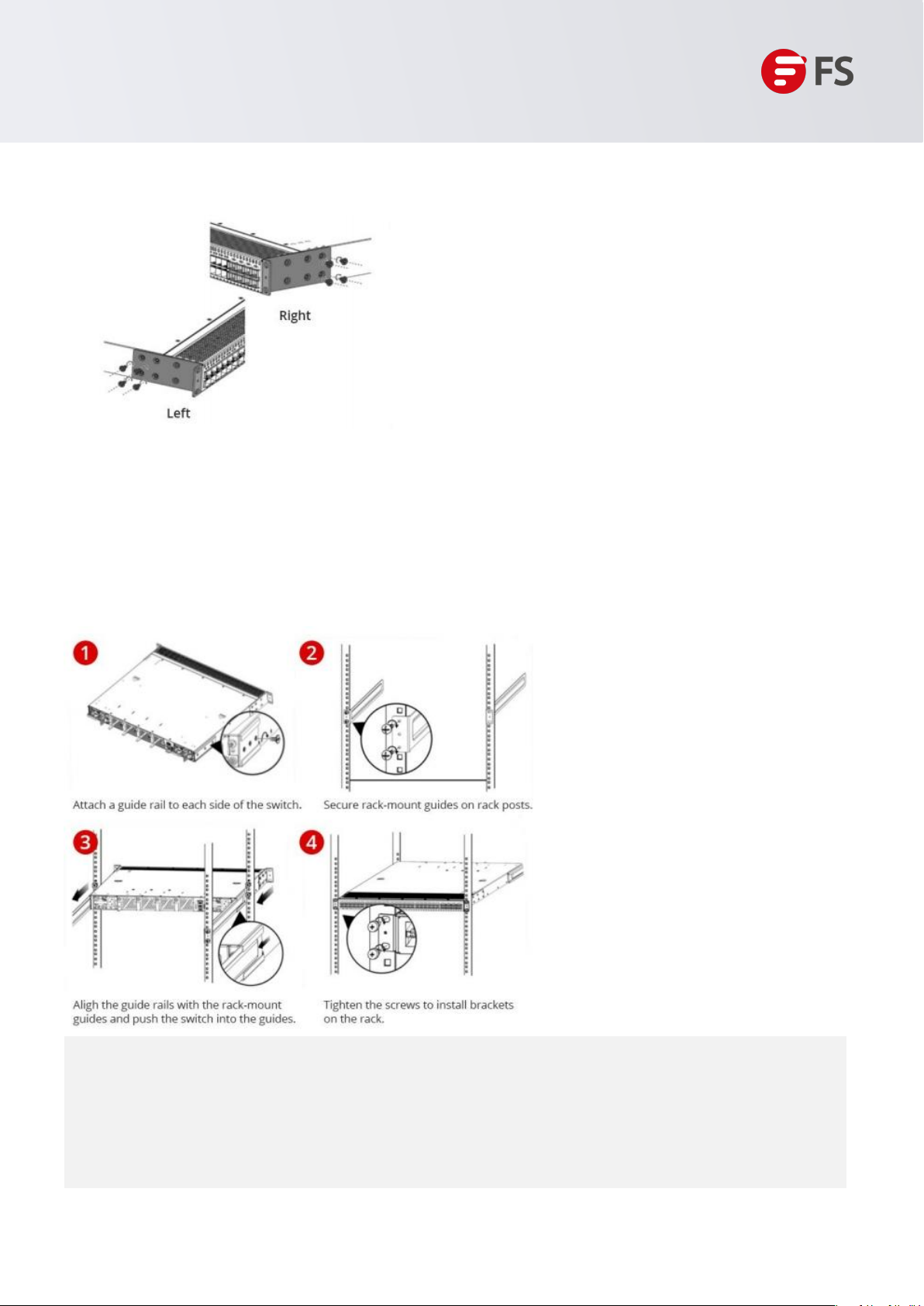
In most cases, users do not have a standard 19-inch rack. Therefore, the most common method is to
place the switch on.
1. Attach four rubber pads to the four corners on the switch bottom.
2. Place the switch on the workbench to allow for adequate airflow.
Figure 3: Mounting the Switch on a Workbench
Hardware Installation and Parts Replacement
Switch Hardware Installation and Maintenance Guide
1.3.2 Mounting the Switch on a Workbench
1.4 Installation and Removal of Modules
1. Remove the new fan module from the packaging box.
2. Hold the handle at the tail end of the fan module and slowly insert it straight along the guide rail until
the fan module is fully inserted into the chassis and securely contacts the fan slot.
3. Use a screwdriver to tighten the screw at the tail end of the fan, securing the fan module in the switch
chassis.
Figure 4: Installing a Fan Module

Innovation · Expertise · Agility 9
•Insert the fan module smoothly and steadily. Pay attention to the orientation of the fan panel and
ensure it is inserted correctly.
•If the module is not aligned properly during insertion, it must be withdrawn and reinserted.
•If you encounter difficulty tightening the screw and it remains loose, it is likely that the fan module is
not fully inserted into the chassis. Please double-check carefully.
•Power supplies and fans with different airflow directions should not be mixed or used
interchangeably.
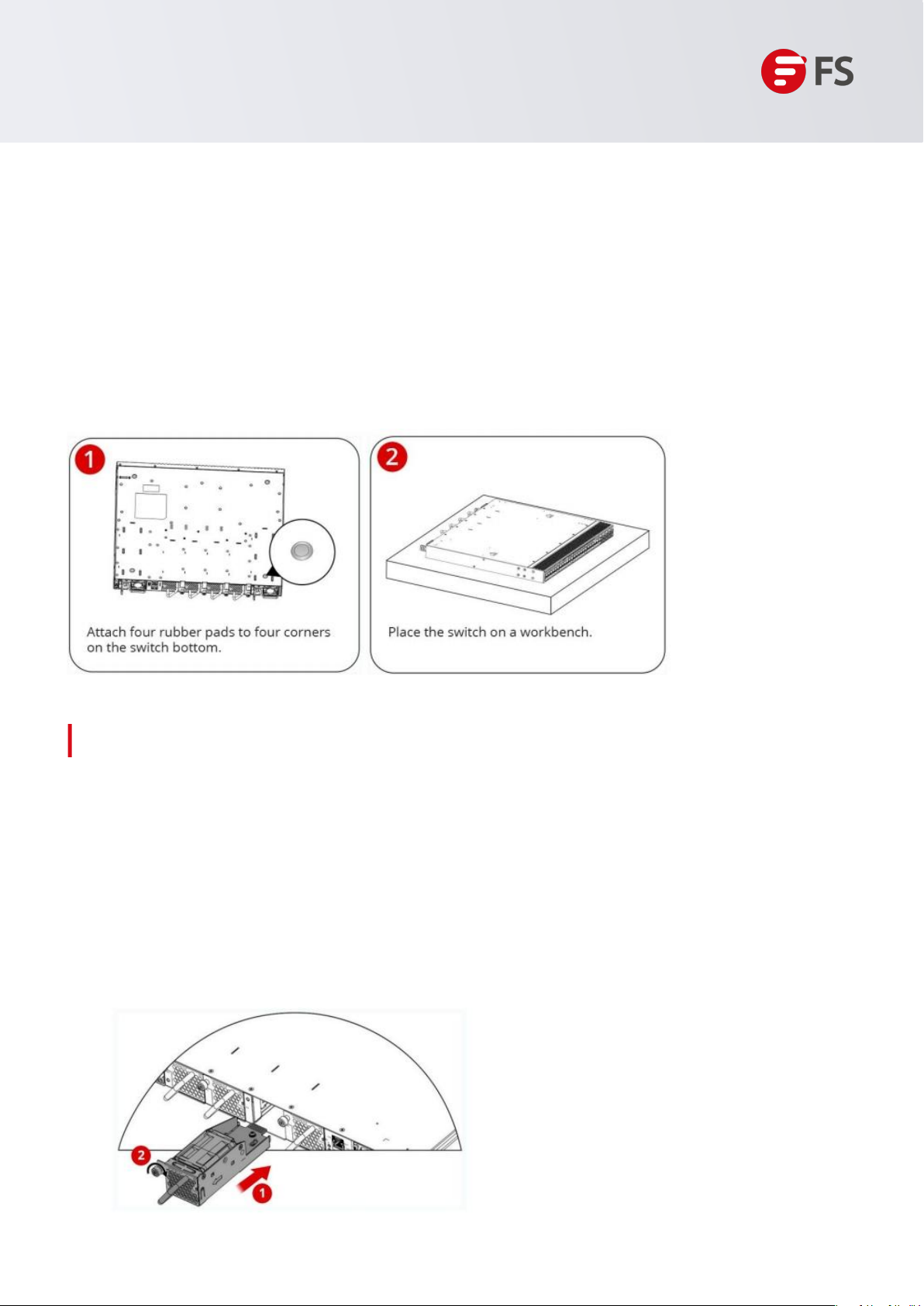
1.4.2 Installing Pluggable Power Modules
•Wear an anti-static wrist strap before the following operations
1. Take out the new power module from the power module packaging box and confirm that the input
method and specifications of the power module match the required ones.
2. Remove the power module barrier. Use the surface with the power nameplate information as the top
panel of the power module. With one hand, grip the handle of the power module, and with the other hand,
support the bottom of the power module. Slowly and steadily insert the power module along the guide
rail until it is completely inserted into the chassis. You will hear a "click" sound, ensuring that the power
module is properly seated in the power slot.
Figure 5: Installing PSM-C150WAC Power Module
Hardware Installation and Parts Replacement
Switch Hardware Installation and Maintenance Guide
Installing PSM-C550WAC Power Module
Altri manuali per S5860 Series
1
Indice
Altri manuali FS Interruttore

FS
FS IES5100-24FS Manuale utente

FS
FS S3910-24TF Manuale operativo

FS
FS S3260-8T2FP Manuale utente

FS
FS S3260-8T2FP Manuale utente

FS
FS S3900 Series Manuale utente

FS
FS N Series Manuale utente

FS
FS S1150-8T2F Manuale utente

FS
FS S5810 Series Manuale utente

FS
FS S3410 Series Manuale utente

FS
FS TAP Series Manuale utente

FS
FS S3400-24T4SP Manuale utente

FS
FS S3410-24TS-P Manuale utente

FS
FS S5860-24XB-U Manuale utente

FS
FS S3200 Series Manuale utente

FS
FS N5860 Series Manuale utente

FS
FS S5800 Series Manuale utente

FS
FS S3700-24T4F Manuale di istruzioni

FS
FS S3950-4T12S-R Manuale utente

FS
FS S5850-24S2C-DC Manuale utente

FS
FS PoE+ Series Manuale utente


