Geosense VWCM-4000 Manuale utente
V 1.3 Feb 19
I
N
S
T
R
U
C
T
I
O
N
M
A
N
U
A
L
VWCM-4000
CRACK METER

V 1.3 Feb 19
2

V 1.3 Feb 19
CONTENTS
Page
1.0 INTRODUCTION 4
1.1 General description 4
1.2 Theory of operation 5
2.0 CONFORMITY 6
3.0 MARKINGS 7
4.0 DELIVERY 8
4.1 Packaging 8
4.2 Handling 8
4.3 Inspection 8
4.4 Storage 9
5.0 INSTALLATION 10
5.1 Getting started 10
5.2 Preliminary tests 11
5.3 Setting distances 12
5.4 Installation - using re-bar anchors 13
5.5 Installation - using mechanical anchors 18
5.6 Installation - using welded anchors 23
6.0 DATA HANDLING 26
6.1 Taking readings 26
6.1.1 Portable readouts 26
6.1.2 Data loggers 26
6.2 Data reduction 27
Calibration certificate 30
6.3 Temperature considerations 31
6.3.1 Thermistor linearization 32
7.0 MAINTENANCE 33
8.0 TROUBLESHOOTING 33
9.0 SPECIFICATION 34
10.0 SPARE PARTS 36
11.0 RETURN OF GOODS 37
12.0 LIMITED WARRANTY 38
3
V 1.3 Feb 19
It is VITAL that personnel responsible for the
installation and use of the VW Crack Meter READ and
UNDERSTAND the manual, prior to working with the
equipment.
1.1 General Description
A Vibrating Wire Crack Meter can be installed singly or included in many types of
monitoring regime and can be linked to various types of readout equipment.
The primary uses for Geosense® VWCM-4000 Cracks Meters are :-
Measure movement of Joints and behaviour of Cracks in Structures.
Measure Joint and Crack movement in Rock Faces
With applications such as, but not limited to, the following :-
Bridges
Dams
Tunnels
Buildings
Rock Faces
Mines
Particular features of the Geosense® VWCM-4000 Cracks Meters are:-
Reliable long term performance.
Rugged; suitable for demanding environments.
High accuracy.
Insensitive to long cable lengths.
The Frequency signals generated by Vibrating Wire instruments are particularly
suitable for the demanding environment of civil engineering applications. The signals
are capable of long transmission distances without degradation. They are also
somewhat tolerant of damp wiring conditions and resistant to interference from
external electrical noise.
The Geosense® range of VWCM-4000 Cracks Meters can be supplied in various
configurations to suit varying installation environments and techniques.
1.0 INTRODUCTION
This manual is intended for all users of VWCM-4000 Crack Meters manufactured by
Geosense® and provides information on their installation, operation and maintenance.
4
V 1.3 Feb 19
1.1 General Description contd
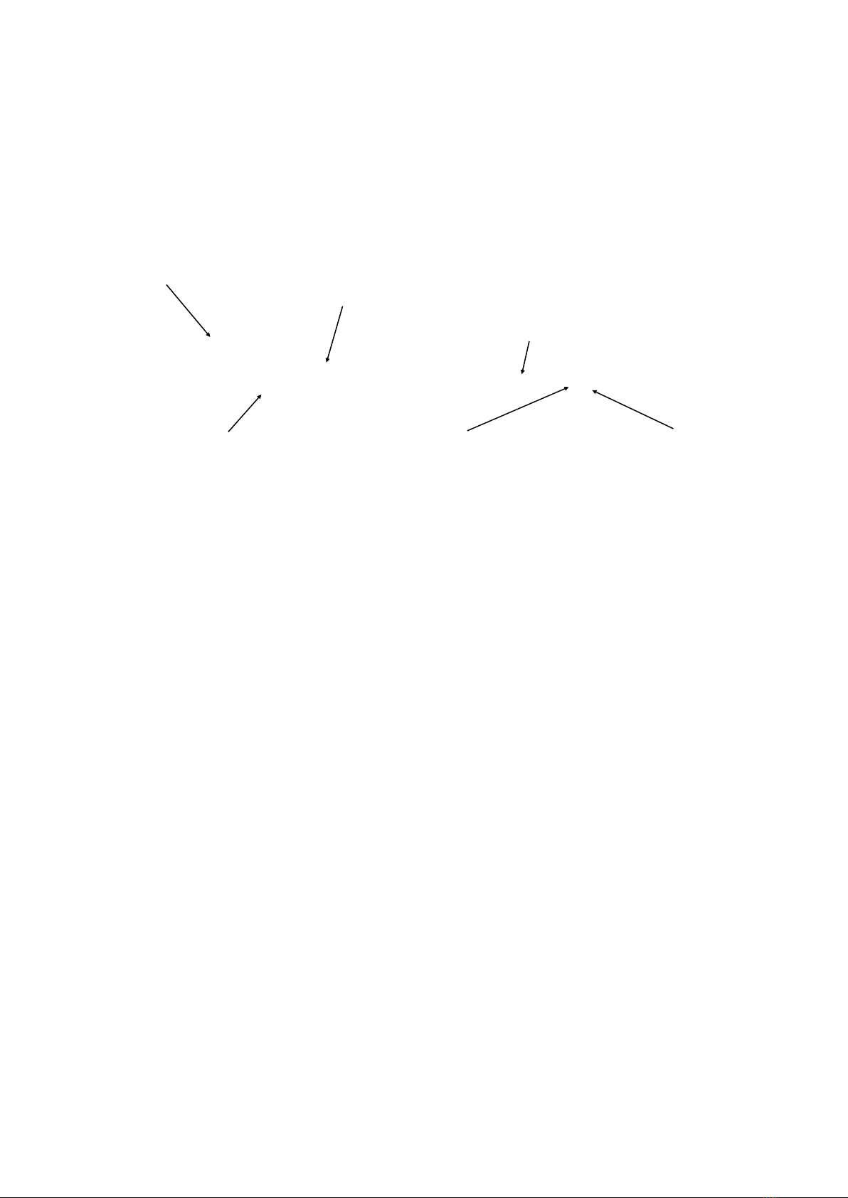
1.2 Theory of Operation
The Geosense® VWCM-4000 Crack Meter is an stainless steel instrument that contains
a VW transducer that is connected to a Calibrated Spring which is in turn connected to
an extending shaft. The ends of the instrument are connected to either side of a crack or
joint so that, as structural movement occurs, the shaft is moved within the housing. The
shaft movement changes the tensions the spring which, in turn, changes the tension in
the vibrating wire. When interrogated, the vibrating wire in the transducer measures its
tension which can be converted to a linear displacement measurement in engineering
units, commonly millimetres.
The internal parts of all Geosense® VWCM-4000 Crack Meters are identical, only the
’Spring Rate’ of the spring and the length changes.
Within the Vibrating Wire transducer coil housing, two coils are located close to the axis
of the wire. When a voltage, or swept frequency excitation is briefly applied to the coils,
a magnetic field is created momentarily, causing the wire to oscillate at its’ resonant
frequency. The wire continues to oscillate for a short time through the ‘field’ of the
permanent magnet, thus generating an alternating current (sinusoidal) output. The
frequency of this current output is detected and processed by a vibrating wire readout
unit or by a data logger equipped with a vibrating wire interface. Readings can be
converted, by calculation, into ‘Engineering’ units.
Vibrating Wire Coil &
Thermistor housing
Housing
Shaft
Sensor cable
Bottom Rose joint (adjustable)Top Rose joint (fixed)
5
V 1.3 Feb 19
2.0 CONFORMITY
Geosense Limited
Nova House
Rougham Industrial Estate
Rougham, Bury St Edmunds
Email: [email protected].uk
Declaration of Conformity
We Geosense Ltd at above address declare under our sole responsibility that the Geosense products
detailed below to which this declaration relates complies with protection requirements of the following
harmonized EU Directives,
Low Voltage Directive 73/23/EEC (as amended by 93/68/EEC)
The Electromagnetic Compatibility Directive 2004/108/EC
The Construction Products Directive 89/106/EEC
Equipment description VW Crack Meter
Make/Brand Geosense
Model Numbers VWCM-4000 Crack Meter Range
Compliance has been assessed with reference to the following harmonised standard:
EN 61326-1:2006 Electrical equipment for measurement, control and laboratory use.
EMC requirements. General requirements.
A technical file for this equipment is retained at the above address.
Martin Clegg
Director
June 2014
6

V 1.3 Feb 19
3.0 MARKINGS
Geosense VW Crack Meter are labelled with the following information:-
Manufacturers name & contact details
Product name
Product Type
Operating Range
Serial number
Electrical Input & Output details
CE mark
7
V 1.3 Feb 19
4.3 Inspection
It is important to check all the equipment in the shipment as soon as possible after
taking delivery and well before installation is to be carried out. Check that all the
components detailed on the documents are included in the shipment. Check that the
equipment has not been physically damaged.
ALL Geosense® VWCM-4000 Crack Meters carry a unique identification serial
number and are supplied with individual calibration sheets.
Calibration Sheets contain VITAL information about the VW
Crack Meter. They MUST be stored in a safe place.
It is suggested that only copies should be taken to site.
4.0 DELIVERY
This section should be read by all users of VWCM-4000 Crack Meters manufactured
by Geosense® .
4.2 Handling
Whilst they are a robust devices, VWCM-4000 Crack Meters are precision
measuring instruments. They and their associated equipment should always be
handled with care during transportation, storage and installation.
Once a shipment has been inspected, it is recommended that VWCM-4000 Crack
Meters remain in their original packaging for storage or further transportation.
Cable should also be handled with care. Do not allow it to be damaged by sharp
edges and do not exert force on the cable as this my damage the internal conductors
and could render an installation useless.
4.1 Packaging
VWCM-4000 Crack Meters are packed for transportation to site. Packaging is
suitably robust to allow normal handling by transportation companies. Inappropriate
handling techniques may cause damage to the packaging and the enclosed
equipment. The packaging should be carefully inspected upon delivery and any
damage MUST be reported, as soon as possible, to both the transportation company
and Geosense.
8

V 1.3 Feb 19
4.4 Storage
All equipment should be stored in an environment that is protected from direct
sunlight. It is recommended that cables be stored in a dry environment to prevent
moisture migrating along inside them in the event of prolonged submersion of
exposed conductors.
Storage areas should be free from rodents as they have been known to damage
cables.
No other special requirements are needed for medium or long-term storage although
temperature limits should be considered when storing or transporting associated
components, such as readout equipment.
9
V 1.3 Feb 19
It is VITAL that personnel responsible for the installation and use
of the VWCM-4000 Crack Meters READ and UNDERSTAND the
manual, prior to working with the equipment.
**********
As stated before, it is vital to check all the equipment in the shipment soon after
taking delivery and in good time before installation is to be carried out. Check that
all components that are detailed on the shipping documents are included.
5.0 INSTALLATION
This section of the manual is intended for all users of VWCM-4000 Crack Meters
manufactured by Geosense® and is intended to provide guidance with respect to
their installation.
It must be remembered that no two installations will be the same and it is inevitable
that some ‘fine tuning’ of the following procedures will be required to suit specific site
conditions.
5.1 Getting started - Preparation for Installation
Prior to installation of a VWCM-4000 Crack Meters it is essential to establish and
confirm details of the installation to be carried out. Some of the main considerations
are listed below :-
1. Intended location and subsequent Protection
2. Expected Movement of the Crack or Joint (see setting range)
3. Anchoring Method
4. Cable routing and marking
The end of the cables connected to VWCM-4000 Crack Meters is marked with the
unique serial number of the sensor to which it is attached.
All instrument cables should be marked with unique identification (e.g. colour codes).
Markings should be repeated at regular intervals along the cable where multiple
cables are to be grouped together, so that in the event of cable damage, there may
be a chance that the identification could be exposed and the cables re-joined
correctly. Multiple cable marks are particularly important close to the end of the
cable. The spacing of markings can vary according to specific site requirements but
a guide of 5m to 10m separation is commonly applied (marking materials available on
request from Geosense).
Cable routing must be carefully considered so as to ensure that it is not vulnerable
from intentional or accidental damage. Vibrating Wire signals can be affected by
electrical interference (EMI), so cable routing should AVOID close proximity to
possible sources.
10
Indice
Altri manuali Geosense Strumento di misura

Geosense
Geosense LS-G6-VW Manuale utente

Geosense
Geosense MEMS DPI I Manuale utente

Geosense
Geosense VWPHT-3600 Series Manuale utente

Geosense
Geosense GXM-300 Series Manuale utente

Geosense
Geosense IPI-V-1 Manuale utente

Geosense
Geosense TP-1 Manuale utente

Geosense
Geosense Quick Joint Manuale utente

Geosense
Geosense WI-SOS 480 Manuale utente

Geosense
Geosense VWLSS-200 Manuale utente


