GOMETRICS T214 Manuale utente

1
DIGITAL MANOMETER T214
© Copyright 2022
Gometrics S.L.
Pol. Ind. Riera de Caldes, C/ Basters 17
Palau-solità i Plegamans - 08184 Barcelona
Tel Sede Central (+34) 93 8646843
Tel Zona Centro (+34) 91 3710042
Web: http://www.gometrics.net
Reference: MI-T214-11-EN
Release: 1.1
Review: March 2023
T214
Digital manometer
USER'S MANUAL
2
EC DECLARATION OF CONFORMITY
The company: GOMETRICS, S.L.
C/Basters, 17 - Polg. Ind. Riera de Caldes
08184 - Palau-Solità i Plegamans (BARCELONA)
Telf.: 00 34 938 646 843 - Fax: 00 34 938 648 218
E-Mail: info@gometrics.net
http://www.gometrics.net
The company declares under its sole responsibility that the device:
Brand name: GOMETRICS
Model: T210 (series)
Type: Digital manometer and milliampere handheld device.
Year of manufacture: 2003
And it is in conformity with Directive 2004/108/EC of the European Parliament and of the Council of 15
December 2004 on the approximation of the laws of the Member States relating to electromagnetic
compatibility and repealing Directive 89/336/EEC.
Harmonised technical standards:
EN 55022:1998 Class B (UNE-EN 61326)
Radiated Emissions.
AT 61000-4-3:2002 (UNE-EN 61326)
Immunity to electromagnetic fields
AT 61000-4-2:1995 (UNE-EN 61326)
Electromagnetic discharges.
AT 61000-4-6:1996 (UNE-EN 61326)
Conducted RF-induced disturbances.
Name: Tomás
Surname de Miguel y de Blas
Job tritle: Managing Director
In Palau -Solità i Plegamans (BARCELONA), 15 February 2012
Fdo.: Tomás de Miguel y de Blas
DIGITAL MANOMETER T214

3
CONTENTS
Table of contents Page
Contents ................................................................................................... 3
Inspection ................................................................................................. 4
Power supply ............................................................................................ 5
Portable operation ................................................................................... 5
Installation............................................................................................... 6
Operation ................................................................................................ 6
Operation as manometer .................................................................... 7
Operation as milli-Ammeter ................................................................ 8
Alternative manometer-milli-ammeter operation ............................... 9
Changing engineering units ...............................................................
10
Quick access to the engineering unit .................................. ..............
11
Instrument messages .......................................................................
11
Installation and use ..................................................................................
12
Adjustments .......................................................................................
12
Input current adjustment ................................................................
12
Input pressure adjustment ............................................................
13
Instrument calibration .........................................................................
13
Guarantee...............................................................................................
13
Technical specifications ...........................................................................
14
Accesories……………………………………………………………............
DIGITAL MANOMETER T214
16
Operating diagram .………………...........................................................
18

4
INSPECTION
The standard instrument is supplied in individual packaging with the following
contents:
- 1 manometer T214
- 1 9 V rechargeable battery, 250 mAh. Ref. EH6LF22H250
- 1 battery charger, Ref. PS 30 B
- 1 set of cables for current measurement. Ref. PN1041
- 1 transport bag, Ref. GOM001
- 1 User's Manual (QR code)*
- 1 certificate of traceability (in attached envelope) or ENAC calibration
certificate (optional)
- 2 washers, U10351620
Please check the contents before using the instrument.
- **1 Ø6mm tube adapter (≤17 bar only ranges). Ref. RBQSF612
DIGITAL MANOMETER T214
* The instructions manual is delivered printed on paper only in the first order or in case
it is specified in the purchase order.

5
POWER SUPPLY
The T214 manometer is designed for portable operation using the supplied
internal battery. This is supplied fully charged but, if the instrument's display
screen does not light up or the LOW BATT message is displayed at switch on,
the battery-charging instructions given on page 11 should be followed.
PORTABLE OPERATION
The T214 manometer is designed for continuous portable operation during
twenty hours.
The instrument uses a NiMH type battery. One of its characteristics is the
reduction of the memory effect with respect to NiCd batteries. This effect
involves a reduction in the battery's recharging capacity. To maintain this
recharging capacity, it is recommended that full recharging and discharging
cycles be carried out. However, although long, its lifetime is limited and in time
will have to be replaced by a new one.
DIGITAL MANOMETER T214

6
INSTALLATION
Follow the procedure provided below to start using the manometer:
1.- Open the battery compartment located at the rear of the instrument and
keep the screws in a safe place.
2.- Insert the battery and close the compartment again.
3.- Turn on the red main switch on the front panel and check that the
verification sequence is initiated on the screen of the model T214, version
V. X.XX and the last units selected on the instrument before it was
switched off, after which the screen will display a ZERO reading or one
close to it and is then ready for operation.
NOTE: If the screen does not light up or the LOW BATT message is displayed,
see page 11.
OPERATION
The T214 instrument has a double operating mode:
. Manometer
. Milli-ammeter
The T214 can operate simultaneously in both modes, although the readings
have to be selected using the key.
DIGITAL MANOMETER T214
4.-With a short press of
key, turns the display to light up.
Press and hold for 2 seconds to turn off the instrument.
Press and hold for 2 seconds to display
and mA
P
every 0.75 sec. the readings.

7
OPERATION AS MANOMETER
Proceed as described below:
1.- Check that the T214 does not have the mA reading indicator active, as
displayed on the left-hand side of the screen by a small arrow. Otherwise
press the key to change the MANOMETER/MILLI-AMMETER so
that the mA indicator is deactivated.
2.- Press the key to change the engineering units in order to verify
the working unit.
WARNING: Pressing the key a single time will display the current unit,
and by keeping it pressed, the work unit will change consecutively. See
page 10 for unit changing and the use of the memories for quick access
to programmed units.
3.- Press the key if the T214 screen displays any reading other
than zero. (NOTE: For absolute sensors not applicable)
4.- Connect the instrument to be calibrated and the pressure input to the
1/8” fitting on top of the T214.
5.- The manometer is now ready to take pressure readings.
DIGITAL MANOMETER T214

8
WARNING: The pressure connection is 1/8-inch BSP M, conical, 60º internal,
and to prevent leaks, one of the two washers supplied at the base of the fitting
connection must be used, Ref. U10351620.
NOTE: GOMETRICS has a pneumatic kit RB400BP01 together with
accessories (up to 20 bar) available that does not require any tools, tightening it
by hand and leak-tight to 20 bar.
GOMETRICS has other connection accessories available from 600 up to 1,000
bar.
OPERATION AS MILLI-AMMETER
The following instruction should be followed when using the T214 for current
readings in the 0-30 mA range, normally to verify the response of a 4-20 mA
pressure transmitter
WARNING: The T214 does not include an internal 24 Vdc power supply and
must be externally powered.
1.- Use the key on the instrument's front panel to select the
current reading mode, which is indicated by the display of the mA icon
on the screen.
2.- The necessary connections should be made using the cables supplied on
the side of the T214 respecting the polarity indicated on the front panel.
3.- The instrument is now ready to take current readings in the range -30 / 0 /
+30 mA.
DIGITAL MANOMETER T214

9
MANOMETER-MILLI-AMMETER ALTERNATIVE OPERATION
Once the T214 is ready for operation in accordance with the section seen on
this and the previous pages, it can be employed for combined reading of
pressure or current by simply using the key on the front panel.
This possibility is specially helpful with pressure and current transmitters.
When the mA icon is visible, the displayed readings are current values. When
this indicator is not visible, the displayed readings are pressure values.
NOTE: The T214 instrument includes current input protection against current
peaks and voltages up to 30 V.
DIGITAL MANOMETER T214
10
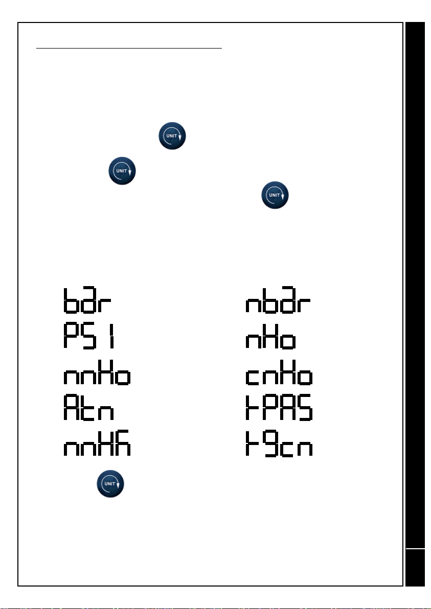
CHANGING ENGINEERING UNITS
The T214 manometer provides the possibility to perform pressure readings in
ten different engineering units.
These units are selected as follows:
1.- Press and maintain the key on the front panel until the desired unit
is displayed.
2.- Release the key when the desired engineering unit is displayed.
3.- Verify the selected unit by briefly pressing the key.
The available units are then displayed on the T214 screen, together with their
corresponding equivalence.
NOTE: The key has two functions:
1.- Pressing it once will display the current unit.
2.- Maintaining it pressed for more than one second will cause the unit to
change, with all those available being displayed consecutively.
BAR
PSI
mm H2O
ATM
mm Hg
miliBAR
m H2O
cm H2O
KiloPascal
Kg/cm2
DIGITAL MANOMETER T214
Indice
Altri manuali GOMETRICS Strumento di misura


