Gooxi SR101 1U Manuale utente

SR101 1U
Rack Server User Manual
Document Version: 02
Release Date: 16/Nov/2022
Shenzhen Gooxi Information Security Co., Ltd.

Statement
Copyright Statement
©Shenzhen Gooxi Information Security Co., Ltd. All rights reserved.
This user manual, including but not limited to all information contained in it,
is protected by copyright law. Without the permission of Shenzhen Gooxi
Information Security Co., Ltd. (hereinafter referred to as "Gooxi"), no imitation,
copying, excerpt, forwarding and other acts or for other purposes.
Disclaimer
Gooxi provides this user manual on an "status quo" basis, and within the
scope of the law, does not provide any express or implied guarantees and
guarantees, including but not limited to commercial sales, suitability for specific
purposes, non-infringement of any rights of others and any guarantee of the use
of this user manual or the inability to use this user manual, and Gooxi does not
provide guarantees for the results obtained from the use of this manual or the
accuracy or reliability of any information obtained through this manual.
Due to the version upgrades or other reasons, the content of this manual
maybe be updated from time to time. Unless otherwise agreed, this manual is
only used as a guide, and the user shall bear all risks of using this user manual.
Trademark Statement
Gooxi®is a trademark of Shenzhen Gooxi Information Security Co., Ltd.
Microsoft®and Windows are trademarks of the Microsoft group of
companies.
Linux®is a registered trademark of Linus Torvalds.
Aspeed®is a trademark of Aspeed Technology Inc.
Other trademarks are the property of their respective owners.

Foreword
This manual is the product technical manual of Gooxi SR101 1U
rackmount server, which mainly describes the appearance, structure, hardware
installation and basic configuration of this product.
This manual is for reference and research by professional technicians. This
product should only be installed and maintained by experienced technicians.
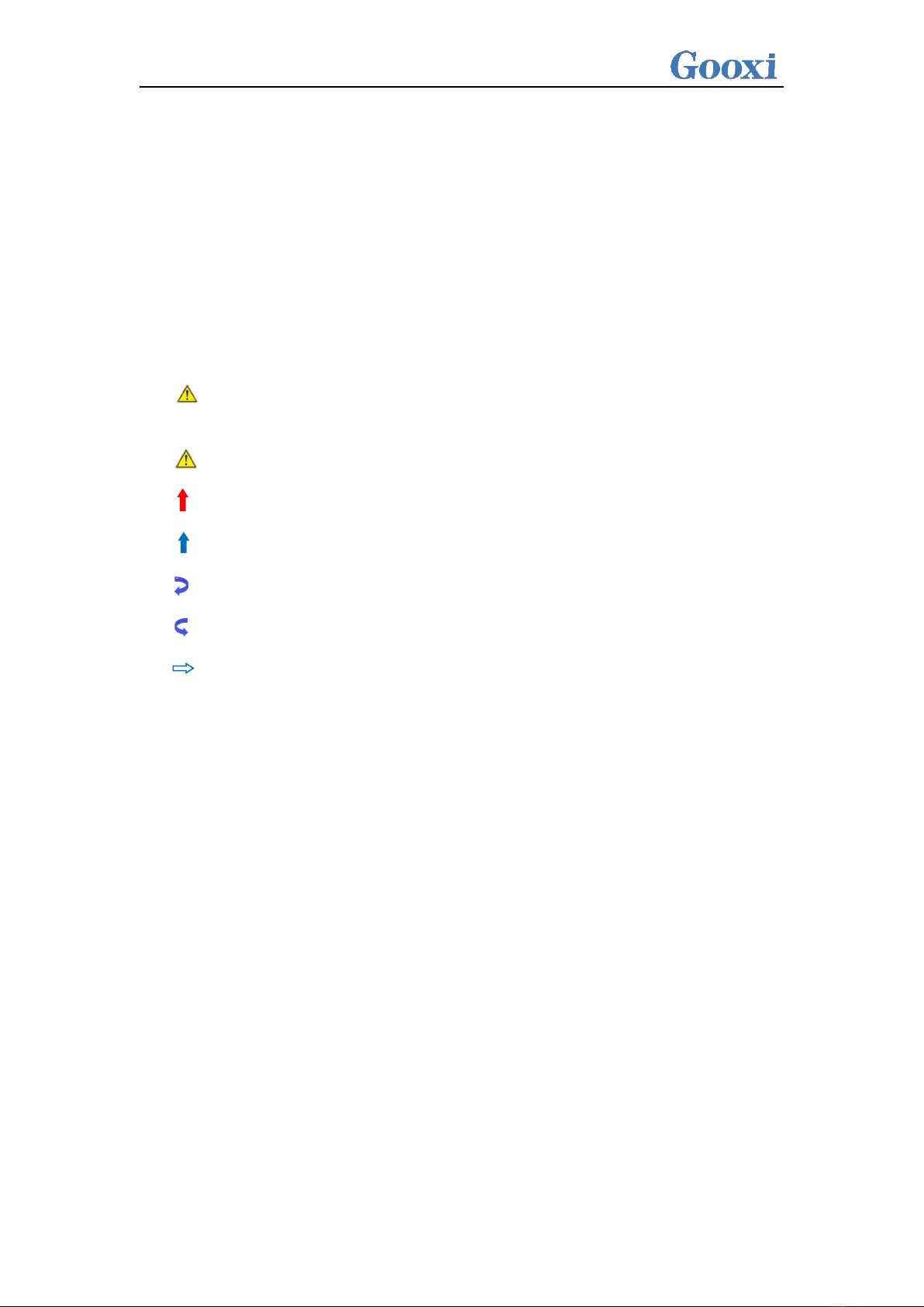
Convention:
Note: it is used to transmit equipment or environmental safety warning
messages, if not avoided, it may lead to equipment damage, data loss,
equipment performance degradation or other unpredictable results.
Warning: indicates a potentially hazardous situation which, if not
avoided, it may result in death or serious personal injury.
Red arrow: means pointing to a certain location.
Blue arrows: means the action of pulling out or inserting at an angle.
Dark blue rotation arrow 1: represents the action of turning the screw
clockwise or pulling it outward.
Dark blue rotating arrow 2: represents the action of turning the screw
counterclockwise or buckling inward.
Hollow arrow: represents the next action or result.

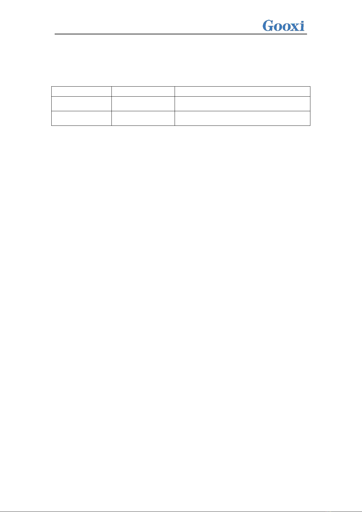
Modification record
Manual version
Release date
Remarks
01
2022/October/16
Initial release
02
2022/November/16
Optimized description

Contents
1 Product Description ...................................................................................................................................................1
1.1 Product overview ............................................................................................................................................... 1
1.2 Product structure ................................................................................................................................................ 3
1.3 Logical structure ................................................................................................................................................ 3
1.4 Product parameters .............................................................................................................................................4
2 Hardware Description ............................................................................................................................................... 6
2.1 Front panel ......................................................................................................................................................... 6
2.1.1 Appearance ......................................................................................................................................................6
2.2 Rear panel .......................................................................................................................................................... 8
2.2.1 Appearance ......................................................................................................................................................8
2.3 Motherboard components .................................................................................................................................11
2.4 Memory ............................................................................................................................................................12
2.4.1 Memory slot location .................................................................................................................................... 12
2.4.2 Memory compatibility information ...............................................................................................................13
2.5 Storage ............................................................................................................................................................. 14
2.5.1 Hard disk configuration ................................................................................................................................ 14
2.5.2 Hard disk serial number ................................................................................................................................ 15
2.5.3 Hard disk status LED .................................................................................................................................... 15
2.6 Power supply ....................................................................................................................................................16
2.7 Fan ....................................................................................................................................................................16
2.8 I/O expansion ................................................................................................................................................... 17
2.8.1 PCIe slot distribution .................................................................................................................................... 17
2.8.2 PCIe expansion module ................................................................................................................................ 17
2.8.3 Hard disk backplane ......................................................................................................................................18
3 Installation Notes .................................................................................................................................................... 20
3.1 Chassis upper cover installation.......................................................................................................................20
3.2 Mounting accessories ....................................................................................................................................... 20
3.2.1 Install the CPU .............................................................................................................................................. 20
3.2.2 Install heat-sink ............................................................................................................................................. 22
3.2.3 Install memory .............................................................................................................................................. 23
3.2.4 Install the server rails .................................................................................................................................... 24
4 Configuration Instructions ...................................................................................................................................... 27
4.1 Initial configuration ..........................................................................................................................................27
4.1.1 Power on ....................................................................................................................................................... 27
4.1.2 Initial data ..................................................................................................................................................... 29
4.1.3 Configure BIOS ............................................................................................................................................ 29
4.1.4 Configure BMC ............................................................................................................................................ 30
5 Appendix ................................................................................................................................................................. 34

1
1Product Description
1.1 Product overview
The SR101 1U rackmount server is a new generation of 2U dual-socket rack server with
a wide range of uses launched by Gooxi for the needs of the Internet, IDC (Internet Data
Center), cloud computing, enterprise market, and telecom business applications. It is suitable
for IT core business, cloud computing virtualization, high-performance computing,
distributed storage, big data processing, enterprise and telecom business applications and
other complex workloads. The server has the advantages of low energy consumption, strong
scalability, high reliability, easy management, easy deployment, etc.
The main configurations are:
·Supports 2 AMD EPYC™ 7003/7002/7001 processors.
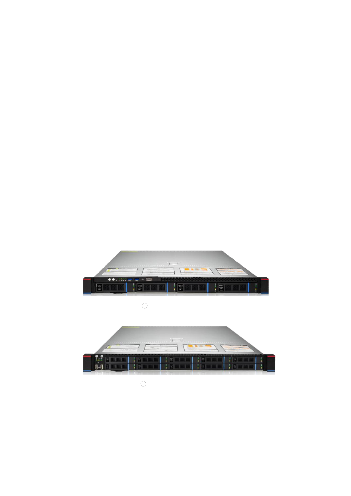
·Supports 2 types of panel frame: ①4*3.5-inch hard disk frame; ②10*2.5-inch hard
disk frame.
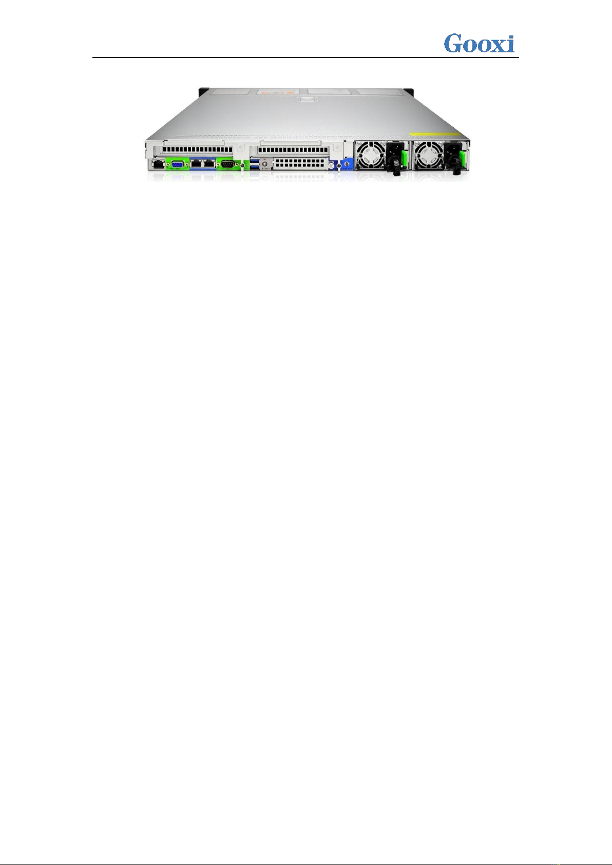
·The rear window supports 2 PCIe expansion slots and 1 standard OCP 3.0 interface.
·The physical picture of the server is as follows:
1SR101-D04R (Figure 1-1)
2SR101-D010R (Figure 1-2)

2
2-PCIe expansion rear window (Figure 1-3)

3
1.2 Product structure
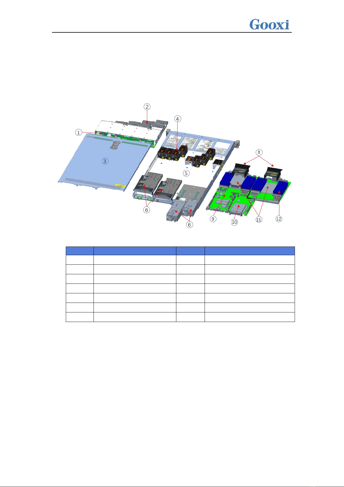
The physical structure of the SR101 1U rack-mounted server is different due to different
requirements, and the configuration will be different. Taking the 10-bay model as an example,
describe the components of the server, as shown in the figure below:
Structure diagram
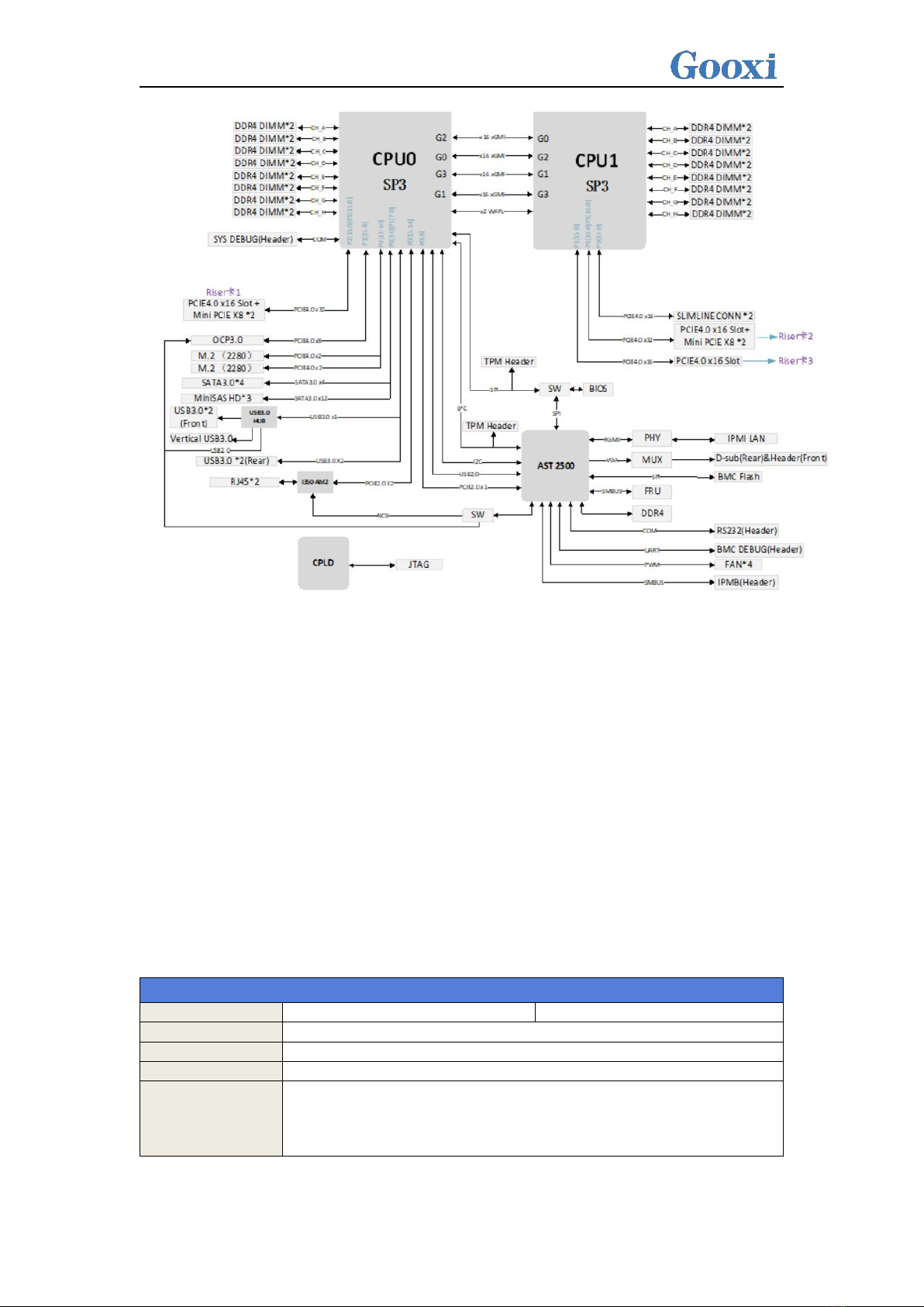
1.3 Logical structure
The logic of SR101 1U rack server is shown in the figure below:
S/N
Name
S/N
Name
1
Backplane
8
Wind shield
2
Hard disk slot
9
Motherboard
3
Upper cover
10
OCP3.0 network card (optional)
4
Fan module
11
CPU cooler
5
Chassis frame
12
Memory
6
PCIe module
7
Power

4
Motherboard logic block diagram
·2 SP3 Sockets, supporting two AMD EPYC™ 7003/7002/7001 series processors;
·Single CPU supports 8 DDR4 channels, each channel supports 2 DIMMs, and the two CPUs
support 32DIMM DDR4 memory;
·G1DLRO-B motherboard provides 2 M.2 M Key SSD slots, only supports 2280 size, PCIe X2
signal;
·2 Gigabit Ethernet ports are integrated on the motherboard, using I350-AM2 chip;
·The BMC chip in this board adopts ASPEED company's AST2500 control chip, which is used
for IPMI remote management, VGA output port, and dedicated Gigabit RJ45 management
network port.
1.4 Product parameters
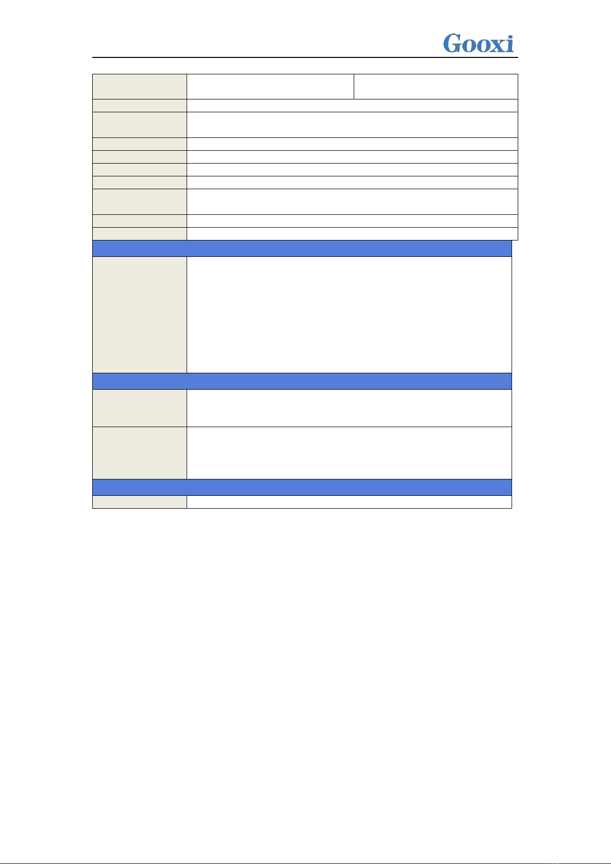
System
System model
SR101-D04R
SR101-D10R/SR101-D10R-NV
Chassis
1U rackmount chassis
Motherboard
G1DLRO-B
CPU
Supports 2 AMD EPYC™ 7003/7002/7001 processors
Memory
Type supports DDR4 RDIMM/LRDIMM;
Frequency supports 2400/2666/2933/3200MHz;
Support single capacity of 8G/16GB/32GB/64GB/128GB/256GB, and the
maximum memory capacity of the whole machine is 8TB.

5
Hard drive
4* 3.5/2.5 inch SATA/SAS hard
drives
10* 2.5 inch SATA/SAS/NVMe
hard drives
Internet function
2 RJ45 Gigabit Ethernet ports
Management
interface
1 RJ45 IPMI management network port
Display function
Onboard Aspeed®AST2500 chip, support VGA output
M.2
Support 2 M.2 ports (M key, only support 2280 size specifications)
USB
Front 2 USB3.0 ports, built-in 1 USB3.0, rear USB3.0 port
Expansion slot
Support 2 PCIe expansion slots
Power
System supports 550W, 800W, 1200W, 1300W, 1600W hot-swap
redundant power supply
Fan
7* 4056 temperature-controlled fans
Size
748mm*433.4mm*43.6mm (length*width*height)
Operating system support
OS
CentOS 7.6/CentOS 8.0
SLES11 SP4
Ubuntu 17.04/Ubuntu 18.04/Ubuntu 20.04
Windows server 2016/Windows server 2019
VMware ESXi vSphere6/VMware ESXi vSphere7
System environment parameters
Operating
temperature and
humidity
Temperature 5℃ ~ 35℃; Humidity: 20% ~ 80% non-condensing
Storage
temperature and
humidity
Short time (≤72 H): temperature -40℃~70℃/ Humidity 20%~90%
non-condensing (including packaging)
Long time (>72 H): temperature 20℃~28℃/ Humidity 30%~70%
non-condensing (including packaging)
Certification
Certification
CE, CCC, ROHS
Indice
Altri manuali Gooxi Server

Gooxi
Gooxi RMC2108-670-HS Manuale utente

Gooxi
Gooxi SL201 Manuale utente

Gooxi
Gooxi R Series Manuale utente

Gooxi
Gooxi SY103-S06R-G2 Istruzioni per il montaggio

Gooxi
Gooxi RMC2108-670-HS Manuale utente

Gooxi
Gooxi SR401 4U Manuale utente

Gooxi
Gooxi Purley Platform 1U Manuale utente

Gooxi
Gooxi ASR4105G-D12R Manuale utente

Gooxi
Gooxi ST401-S36REH-G2 Istruzioni per il montaggio

Gooxi
Gooxi SR201 2U Manuale utente