HF Scientific Micro TOL Manuale utente

OWNERS MANUAL
Micro TOL
0-1000 NTU
HF scientific, inc.
3170 Metro Parkway
Ft. Myers, FL 33916
Phone: 239-337-2116
Fax: 239-332-7643
Website: www.hfscientific.com
Catalog No. 24031 (12/04)
Rev. 2.7


MICRO TOL (12/04)
REV. 2.7
DECLARATION OF CONFORMITY
Application of Council Directive
Standard to Which Conformity is Declared:
Product Safety - Tested and passed CE EN61010-1: 1990 + A1: 1992 (73/32 EEC)
- Tested and passed ETL (tested to UL3111-1)
- Tested and passed ETLc (tested to CSA C22.2#1010-2-010)
Immunity – Tested and passed EN61326: 1998
Including:
EN61000-4-2
EN61000-4-3
EN61000-4-4
EN61000-4-5
EN61000-4-6
EN61000-4-8
EN61000-4-11
Emissions - Tested and passed EN61326 (EN55011 Class B)
Manufacturer’s Name: HF scientific, inc.
Manufacturer’s Address: 3170 Metro Parkway, Fort Myers, Florida 33916-7597
Importer’s Name:
Importer’s Address:
Type of Equipment: Process Turbidimeter
Model No: Micro TOL
I, the undersigned, hereby declare that the equipment specified above conforms to the
above Directive and Standard
Place: Fort Myers, Florida USA
(Signature)
Robert J. Maley, President

MICRO TOL (12/04)
REV. 2.7

MICRO TOL (12/04)
REV. 2.7
Table of Contents
Specifications.................................................................................................................1
1.0 Overview............................................................................................................2
1.1 Unpacking and Inspection of the Instrument and Accessories .............2
1.2 The Display ...........................................................................................2
1.3 The Touch Pad ......................................................................................3
1.4 Vapor purge ...........................................................................................4
2.0 Safety .................................................................................................................5
3.0 Installation and Commissioning .......................................................................6
3.1 Mounting and Site Selection..................................................................6
3.2 Plumbing ..............................................................................................7
3.2.1 Pressurized Systems...................................................................8
3.2.2 Drain Vent..................................................................................8
3.3 Electrical Connections ..........................................................................8
3.3.1 Power ........................................................................................9
3.3.2 RS-485 Option ..........................................................................9
3.3.3 Relays.........................................................................................9
3.3.4 4-20 mA ....................................................................................9
4.0 Operation .........................................................................................................10
4.1 Routine Measurement .........................................................................10
4.2 Security Access Feature.......................................................................11
5.0 Instrument Calibration ....................................................................................12
5.1 Calibration Standards ..........................................................................12
5.2 Calibration Procedures ........................................................................12
6.0 Instrument Offset ........................................................................................... 15
6.1 Indexing Calibration Cuvettes ............................................................16
6.2 Restoring Factory Settings...................................................................16
7.0 Instrument Configuration (CONFIG mode) ....................................................17
7.1 Displayed Resolution ..........................................................................17
7.2 Setting the Year....................................................................................17
7.3 Setting the Day and Month .................................................................18
7.4 Setting the Time...................................................................................18
7.5 Programming the Alarms & 4-20 mA (if used) ..................................19
7.5.1 Alarm 1 ....................................................................................20
7.5.2 Alarm 2 ...................................................................................21
7.5.3 Setting the 4-20 mA Output (O/P) ..........................................21
7.6 Configuring the RS-485 I/O Port (if equipped)...................................22
7.7 Setting the Security Access..................................................................25
7.8 Saving Configuration Settings.............................................................25
8.0 Troubleshooting & Maintenance ....................................................................26
8.1 Micro TOL Fault Detection.................................................................26
8.2 System Fail Message ...........................................................................26
8.3 Diagnostic Chart .................................................................................27
8.4 Technical and Customer Assistance ...................................................27

MICRO TOL (12/04)
REV. 2.7
Table of Contents (continued)
9.0 Routine Maintenance.......................................................................................28
9.1 Cleaning the Flow Through Cuvette ...................................................28
9.2 Replacing or Installing the Desiccant Pouch ......................................28
9.3 Replacing the Source Lamp ................................................................29
9.4 Replacing the Battery ..........................................................................29
10.0 Accessories and Replacement Parts List .........................................................29
11.0 Warranty .........................................................................................................30

MICRO TOL (12/04)
Rev. 2.7 1
Specifications
Measurement Range .01 – 1000.0 NTU
Accuracy
±2% of reading plus 0.01 NTU (0-10 NTU)
±5% of reading plus 0.1 NTU (10-1000 NTU)
Resolution 0.0001 NTU (below 10 NTU)
Response Time 0 - 8 Seconds (0 – 10 NTU Range)
0 – 20 Seconds (0-1000 NTU Range)
Display Multi-Line Liquid Crystal Display
Two User Programmable
Alarms & Analog Output 120-240VAC 2A Form C Relay & 4-20 mA
Communications Port Bi-directional RS-485 (optional)
Maximum Water Pressure 414 kPa (60 psi.)
Flow Rate 100 ml/min. – 6 liters/min. (.026-1.5 Gal/min)
Operating Temperature Range 1°C – 50°C (34°F – 122°F)
Sample Temperature Range 1°C – 50°C (34°F – 122°F)
Power Supply Voltage 90 – 250 VAC, 47 – 63 Hz
Power Consumption 80 VA
Insulation Rating Double Insulated, Pollution Degree 2, Overvoltage Category II
Environmental Conditions Not recommended for outdoor use.
Altitude up to 2000 meters
Up to 95 % RH (non-condensing)
Enclosure Rating IP 66 /NEMA 4X
Regulatory Compliance
(0-10NTU)
(20023) White Light Version compliant to U.S. EPA 180.1
(20024) Infrared Version compliant to ISO 7027
Shipping Weight 2.5 kg (5.5 lbs.)
Warranty 1 Year from date of shipment

MICRO TOL (12/04)
Rev. 2.7 2
1.0 Overview
The MICRO TOL process turbidimeter allows you to measure the turbidity of your
process water on-line. The White Light MICRO TOL has been designed to meet the
design criteria specified by the US EPA on turbidity measurement. The infrared MICRO
TOL was designed to meet the design criteria specified in ISO 7027 and DIN 27027 for
the measurement of the turbidity of a sample. Both models have long life lamps.
1.1 Unpacking and Inspection of the Instrument and Accessories
The table below indicates the items you should find in your turbidimeter shipment.
Item Part # Quantity
MICRO TOL Turbidimeter 20023 (White Light Version), or
20024 (Infrared Version) 1
Instruction Manual 24031 1
Desiccant Pouch 21555R 1
Cuvette (Single Pack) 50033 1
Tubing Kit * 51025A 1
* Note - Tubing Kit includes:
1-shutoff clamp
1-backpressure valve
2-connecting tubings with fittings for flow through assembly
1-drain vent screw (used in pressurized systems)
Remove the instrument from the packing carton. Carefully inspect all items to ensure
that no visible damage has occurred during shipment. If the items you received do not
match your order, please immediately contact your local distributor or the HF scientific,
inc. Customer Service department.
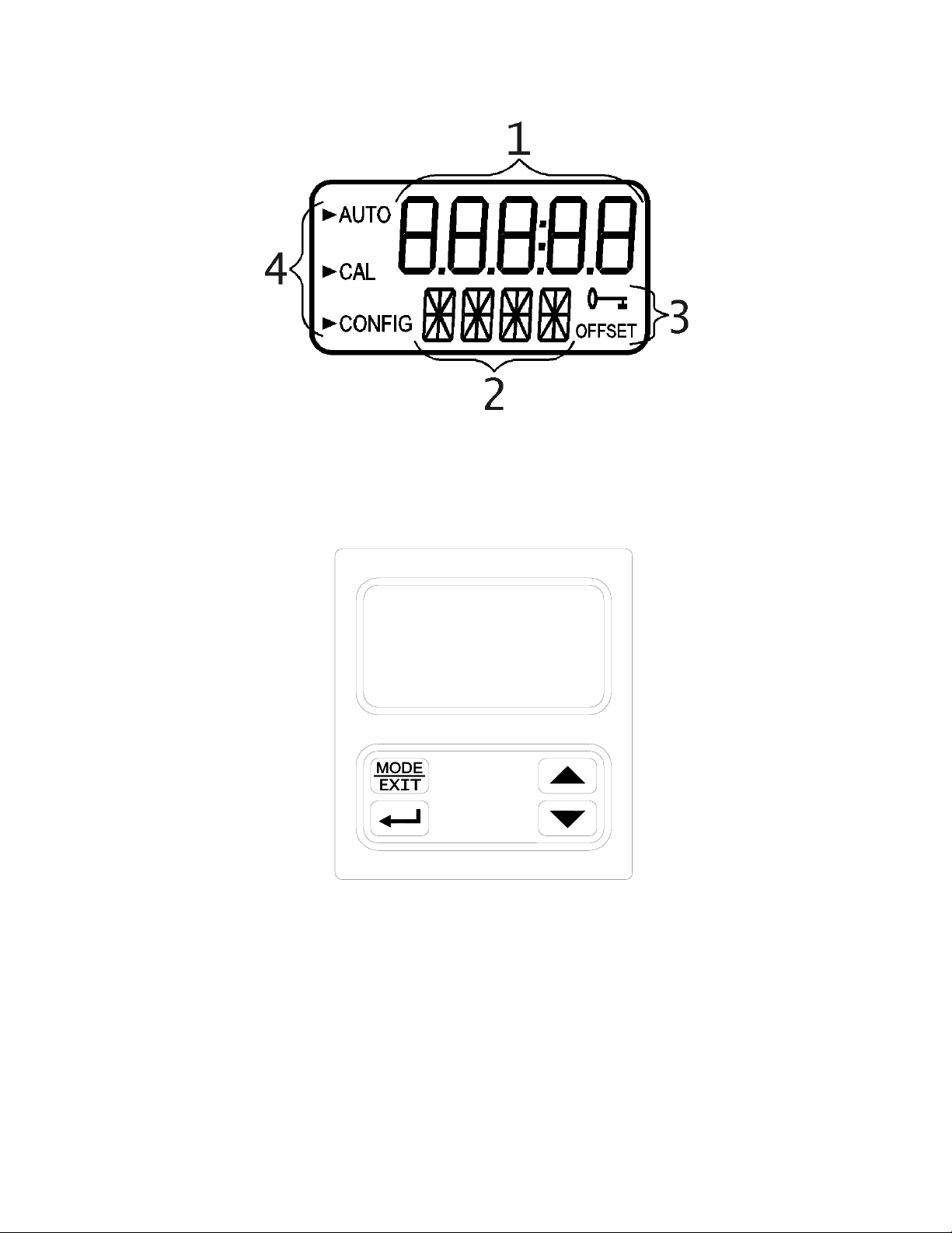
1.2 The Display
Figure 1 illustrates all the items that can appear on the display. The upper row of the
display (1) is used for reporting the turbidity levels and to provide user guidance in the
customer setting routine. The lower row of the display (2) is used to communicate error
messages and provide user guidance. The display has two icons (3) that are used to
indicate the use of access code and offset mode. In addition, mode arrows (4) are used to
indicate the current instrument operating mode; AUTO (normal operation), CAL
(calibration) and CONFIG (configuration).
MICRO TOL (12/04)
Rev. 2.7 3
Figure 1 – Display used in the instrument.
All items used on the display are shown in this figure
1.3 The Touch Pad
Figure 2: The Micro TOL touch pad.
Figure 2 illustrates the touch pad. The touch pad has four buttons: MODE/EXIT, ↵, t,
and u. The MODE/EXIT button is used to cycle between the four operational modes of
the instrument: CAL, CAL OFFSET, CONFIG, and AUTO (Measurement) mode. The
↵button enters the option (or mode that is highlighted or chosen. The tand ubuttons
are used to scroll through lists and to increase or decrease settings.

MICRO TOL (12/04)
Rev. 2.7 4
1.4 Vapor purge
The Micro TOL is equipped with a continuous vapor purge system. A replaceable
desiccant pouch in the lower portion of the instrument dries the air. System heat is used
to warm the air. A fan inside the instrument continuously circulates heated dry air around
the optical well and the flow through cuvette. This feature eliminates the need for a dry
purge line.
The Micro TOL monitors the replaceable desiccant pouch condition continuously. The
LCD display will show DESC on the lower line in the event that the desiccant pouch
needs replacement. Replacement desiccant pouches are available from HF scientific, inc.
or your local representative (part # 21555R).
Indice
Altri manuali HF Scientific Strumento di misura


