Hiking DTS238-7 Manuale utente
DTS238-7 WIFI type multi-function smart energy meter is designed to measure three phase four wire C active
energy and variable parameter. The meter have RS485 communication port and WIFI communication, it can use
PP for remote reading and control on/off. ll of its functions comply with the relative technical requirement for
class 1 three phase watt hour meter in IEC62053-21 and its data communication rules obey the requirement of
MODBUS-RTU and WIFI 802.11b/g/n.It is a long life meter with the advantage of high stability , high over load
capability , low power loss and small volume .
The meter should be installed in suitable environment with ambient temperature range between-25°+55°,the
relative humidity less than 75% and temperature limits between and-40°+70°.
The meter is manufactured complying with international standard IEC62052-11 on Electricity metering
equipment ( C) General requirements tests and test conditions and IEC62053-21 on Static meters for active
energy (classes 1 and 2).
2.Specification and Technical Parameters
2.1Specification
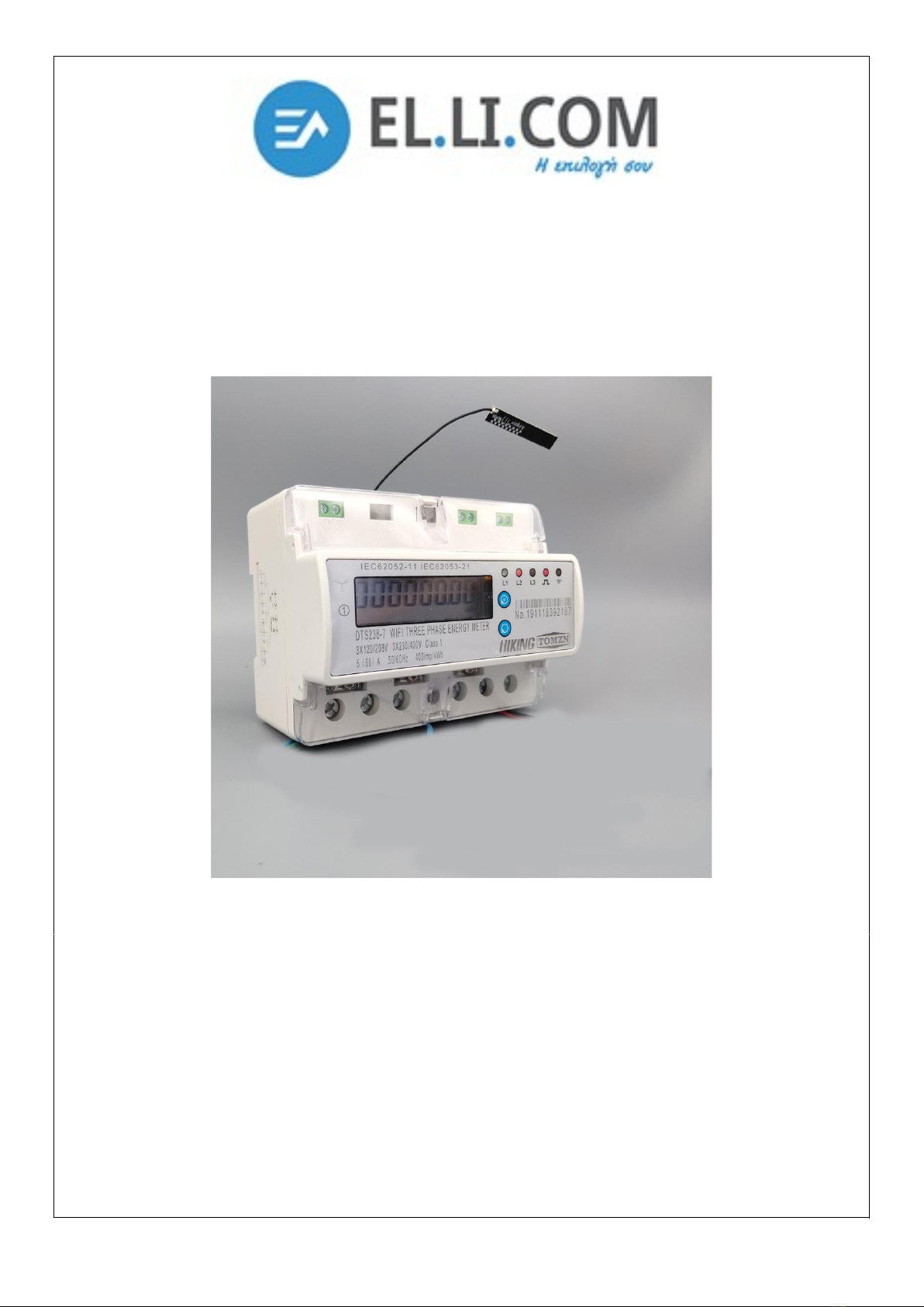
Din rail , 3 phase wifi smart energy meter
Type: DTS238-7
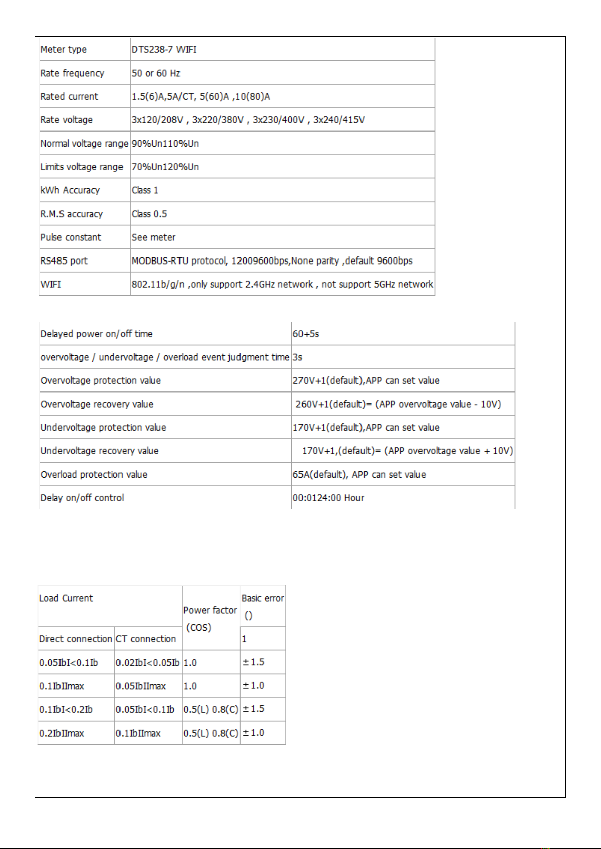
2.2 basic parameters
Note: when it happens interrupt power-supply , the meter will not cut off , undervoltage event must last 3s , then
it will cut off.
2.2 Technical Parameters
2.2.1Basic tolerance
2.2.2Self-consumption
Current circuit is less than 1.5V / each phase
Voltage circuit is less than 2W/8V each phase
2.2.3Starting current
Under the rated voltage , rated frequency and COS=1 , the meter shall start and continue to register on
application of 0.2% In (if CT is used) or 0.4% Ib .
2.2.4 nti-creeping
The meter has anti-creeping logical circuit. When 115%Un is connected to the meter and current circuit is cut
, the meter shall not create more than one pulse in a stipulated time
2.2.5 verage-life
The meter can be used for at least 10 years in normal operation specified in this manual
2.2.6LCD: 6+2 (999999.99kWh)
3.Basic Features
3.1 Measuring positive & negative active energy with negative energy accumulated into positive energy,.
3.2The meter also display three phase real voltage , real current , real active power , real power factor , real
frequency
3.3 Pulse LED indicates working of meter,Pulse output with optical coupling isolation
3.4 RS485 communication port and WIFI communication
3.5 Measuring active energy without calibration under long term operation
3.6 display step by step with button
3.7 it can use PP software for data reading and remoter control on/off.
3.8 it has overvoltage and undervoltage protection , it can set value from PP
3.9 it has overload protection ,it can set value from PP
3.10 it has timing control function , it can set value from PP
3.11 it can reset the active energy to zero from PP
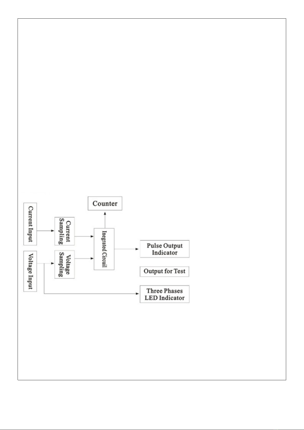
4.Working principles
Three phase voltage and current are sampled from respective sampling circuit and transformed into suitable
signal, which is carried into integrated circuit , then the meter output pulse signal in positive appropriation to
measured power to drive step-motor counter or LCD counter to realize energy measurement. The meter has
energy pulse output for testing with pulse width of 80+20ms
Diagram for Working Principles
5. Structure
The meter consists of meter base , meter cover , terminal base , terminal cover . there are lead seal on
meter cover and terminal cover . special screw is used to fix the terminal cover on which a lead seal can be
installed
6. Usage
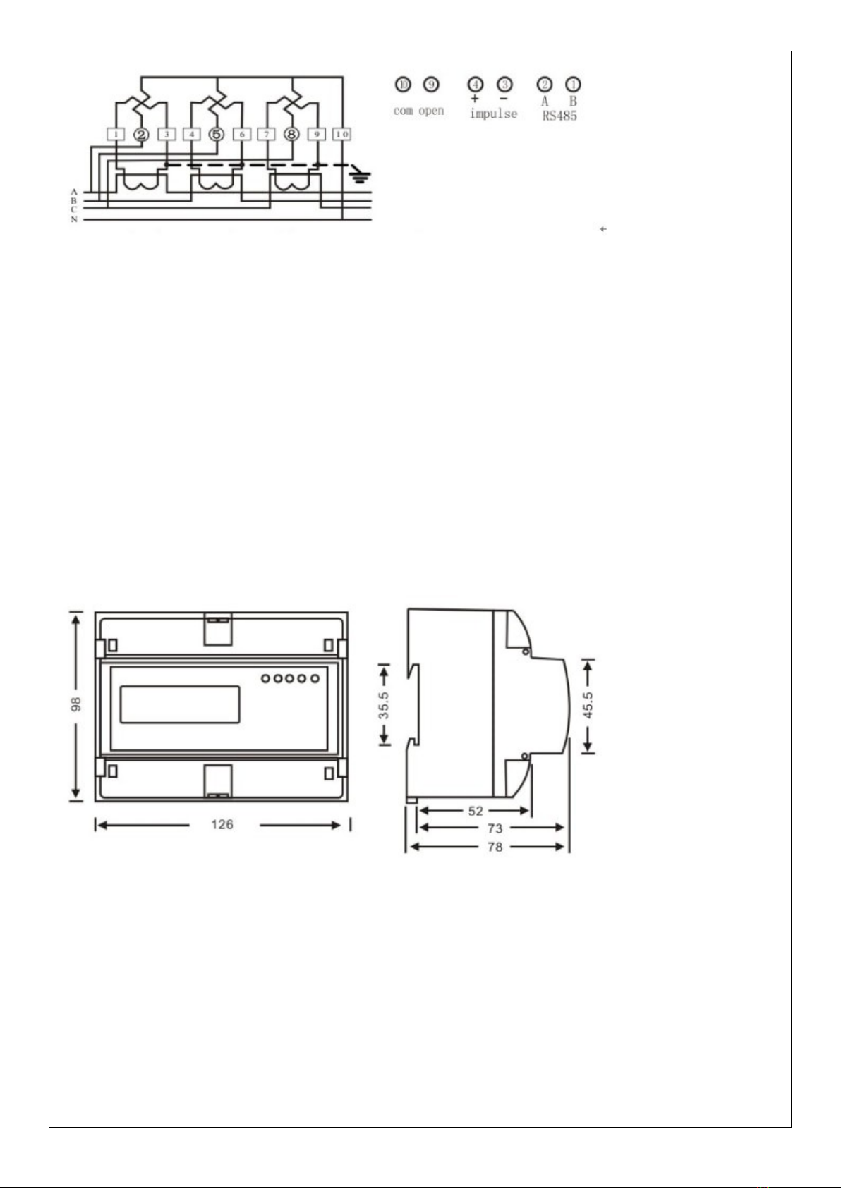
6.1 schematic diagram
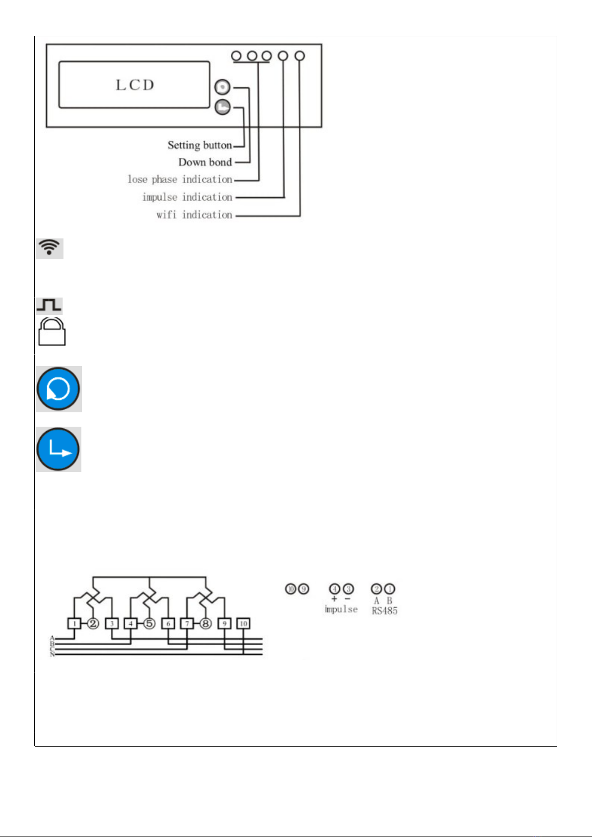
WIFI led indication, if you push the setting button last 5s, the WIFI led will flash 1s interval ,its means
meter enter into the status of waiting for WIFI distribution network . if WIFI led light on 5s , light off 0.1s ,it means
meter connect the WIFI successfully.
Impulse led indication: it will flash with different speed according the current load of the meter
Relay off signal : the signal display on LCD means relay switch off .
Down bond: you can push this button to check the different data display , it will reset the resettable
active energy to zero when you push this button last 5s ,but total active energy will not reset.
Setting button: if you push the setting button last 5s ,meter will enter into the status of waiting for WIFI
distribution network .if you want to reset status of WIFI distribution network, you also can push the setting button
last 5s.
6.1 Connection diagram
(current wire bottom in and bottom output)
Direct input type connection diagram
(current wire bottom in and bottom output)
Transformer input type connection diagram
Noting: for CT input type connection , the power consumed display in register is not fact power consumed. The
fact power= the power display in register of meterX CTrate. For example , the power display in the register is 0.5
kWh and the CT is 800/5 , the fact power consumed=0.5 kWh X 160=80kWh
-
6.2 Installation
The meter can be installed on a35 mmDIN rail
6.2.1The meter can not installed and used until it is checked goods and sealed before delivery
6.2.2The meter should be install in the water proof box indoor or outdoor . the meter's box should be fixed on
strong and flame-resistant wall with a recommended height of about1.8 m, where there is no corrosive gas
around .
6.2.3The meter should be install fully in accordance with connection diagram on the terminal cover, it is better to
use copper as the leading wire for connection. ll screws should be tightened.
6.2.4Diagram for installation dimension
7. Transportation and Storage
7.1 Heavy impact should be burdened to the products while transportation and unpacking.
7.2 The products should be stored in the original package and kept in place with temperature between-
40°+70°,the relative humidity less than 75% and no corrosive gas around .
7.3 Instorehouse , the meter should be placed on the shelf when kept in stock , there should not be more than 7
cartons piled up in vertical. Single-packed meters can not be piled up with more than 5 meters in vertical.
8. Warranty period
Within 12 months from the day of selling and provided that users operate correctly according to the requirement
of the user's manual , if the meter doesn't reach its technical specification. It can be repaired or replaced in free f
charge by the manufacturer .
9. Frame format
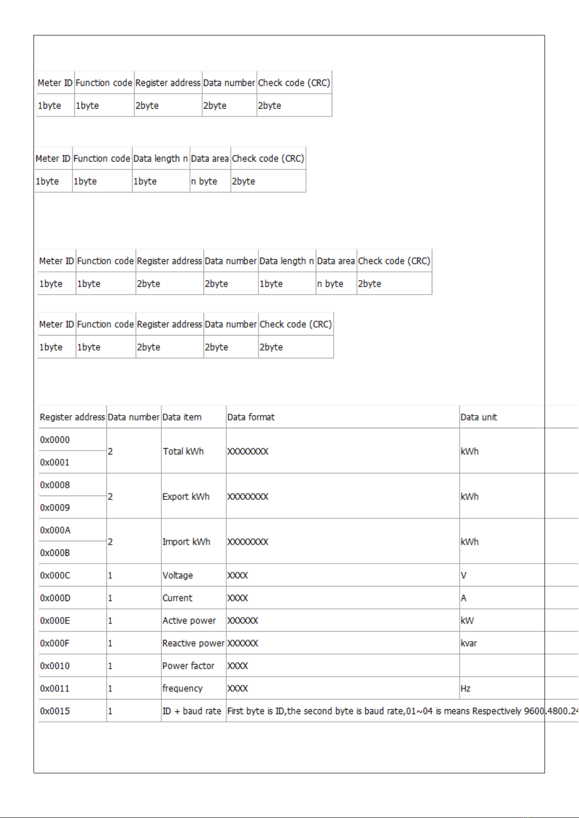
9.1 Read command(function code 03)
Send frame
Receive frame
9.2 Write command(function code 10)
Send frame
Receive frame
9.3 Energy meter register address
Note 1: one register address is store 2 byte data ,so the data length read as 4 byte when data number is 2 .
Note 2::you can use ID ID(0x00) to broadcast and got data when you do not know the meter ID. But this ways is
only for 1 pcs meter to connection on RS485 wire
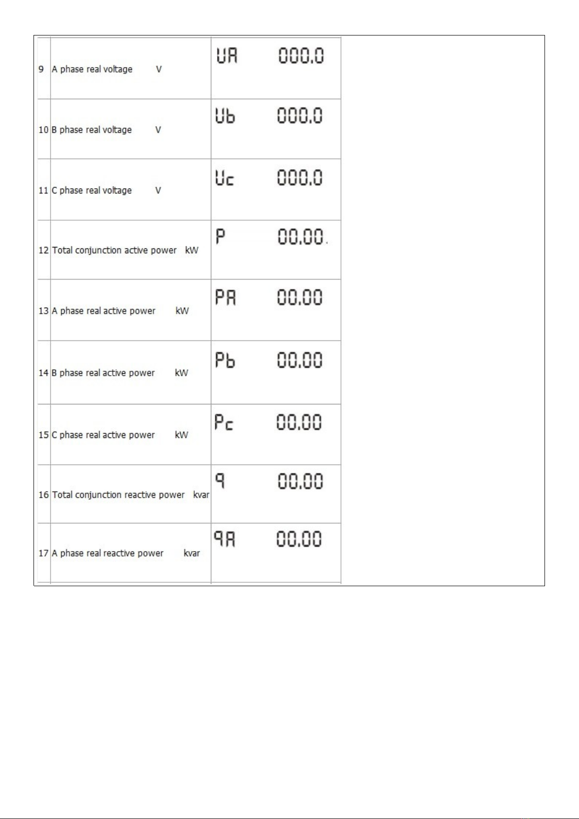
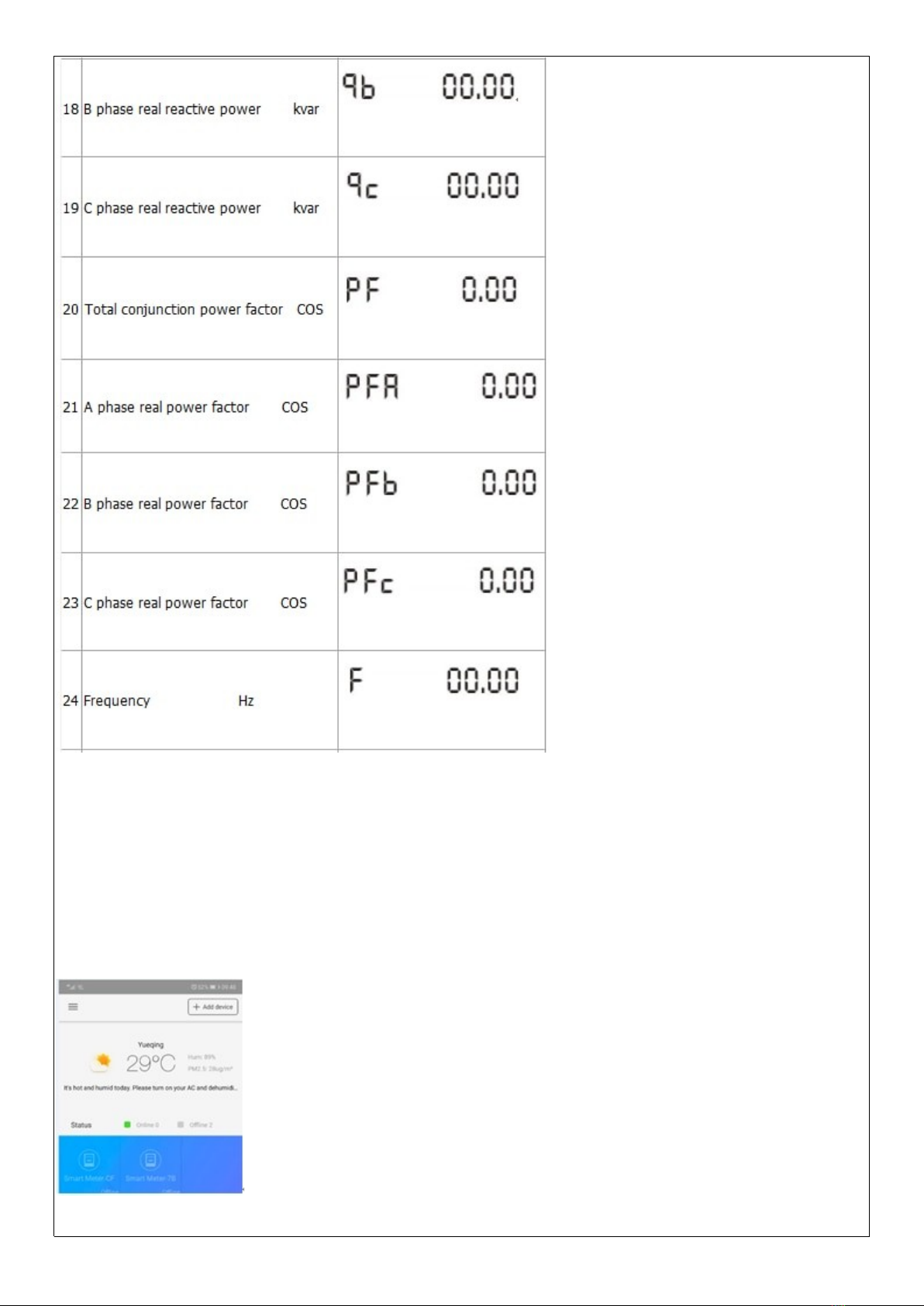
10. Display item
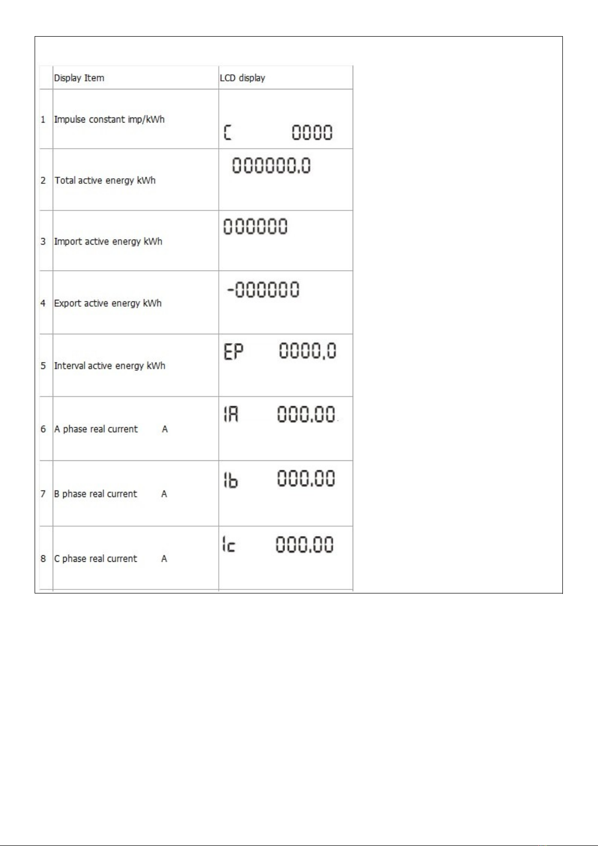
Display item:
Please scan the two-bar-codes to download the WISEN software
. Meter input power
When the meter power on , you can push the setting button last 5s , meter enter into the status of waiting for
WIFI distribution network and the WIFI led will flash 1s interval .
its means meter enter into the status of waiting for WIFI distribution network . if WIFI led light on 5s , light off 0.1s
,it means meter connect the WIFI successfully.
. dd device
Please check firstly that your telephone have connected the available WIFI network , then click the add device
button .now the meter only used under 2.4GHz WIFI network , it can not use under 5GHz WIFI network .
Select the WIFI distribution network
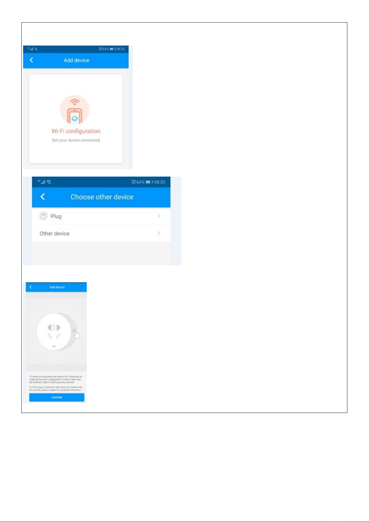
Select the Plug
You can push the setting button last 5s , meter enter into the status of waiting for WIFI distribution network , then
click confirm button
Input the WIFI network account and password , then confirmed to next step
Altri manuali Hiking Strumento di misura


