
Hioki TM6101 Manuale utente


Contents
i
1
2
3
4
5
6
7
8
9
10
付
録
索
引
11
12
Contents
Introduction.................................................................................1
Confirming Package Contents....................................................2
Safety Information ......................................................................3
Operating Precautions................................................................4
Chapter 1
Overview __________________________________ 11
1.1 Product Overview and Features .......................................11
1.2 Names and Functions of Parts ..........................................13
1.3 External Dimensions .........................................................15
1.4 Measurement Flowchart ...................................................17
Chapter 2
Measurement Preparations___________________ 19
2.1 Installation & Connection Procedures ...............................19
2.2 Installing the Software .......................................................20
System Requirements ......................................................................20
Recommended System ....................................................................20
Installing Hardware Drivers ...............................................................21
Installing PC application software .....................................................22
2.3 Install the Ferrite Cores .....................................................23
2.4 Connecting the Sensor Unit ..............................................24
2.5 Connecting the USB Cable ...............................................25
2.6 Connecting the AC Adapter ..............................................26
2.7 Configuring the Instrument for Measurement ...................27
Setting the Measurement Mode ........................................................27
Setting the Sensitivity Range ............................................................28
Setting the Integration Time ..............................................................28
Configuring Auto-range Operation ....................................................29
Setting the Detection Level Upper and Lower Limits ........................29
Setting the Average Times ...............................................................29
Setting a Trigger ...............................................................................30
Setting Calculation Data ...................................................................30
Performing Dark Correction ..............................................................30
2.8 Using Correction Functions ...............................................31
Dark Correction .................................................................................32
Chromaticity Correction ....................................................................33
Illuminance Correction ......................................................................34
Luminous Intensity Correction ..........................................................34
Luminous Flux Correction .................................................................34
TM6101A981-05

Contents
ii
Chapter 3
Measurement ______________________________35
3.1 Pre-Operation Inspection .................................................. 35
3.2 Measurement .................................................................... 38
Conducting Measurements Using the PC application software ....... 38
Building Software and Making Measurements Using Library Functions ... 38
3.3 Measurement Example ..................................................... 39
Measuring CIE Averaged LED Intensity, Chromaticity,
and Other Properties ........................................................................ 39
Measuring Total Luminous Flux, Chromaticity,
and Other Properties Using an Integration Sphere .......................... 40
Measuring the Brightness, Chromaticity,
and Color Rendering Index of a Light .............................................. 41
More Rigorous Chromaticity and Luminous Intensity Measurement
(Comparison with a Calibrated Sample) .......................................... 42
Chapter 4
External Control ____________________________43
4.1 External Input/Output Connector and Signals .................. 43
Connector Type and Signal Pinouts ................................................. 44
4.2 Timing Chart ..................................................................... 46
4.3 Internal Circuitry ................................................................ 48
Electrical Specifications ................................................................... 49
Connection Examples ...................................................................... 50
4.4 External I/O Settings ......................................................... 51
Setting Signal Output after the Completion of Measurement
(INDEX Setting) ................................................................................. 51
Setting the Trigger (TRIG) Signal Logic ............................................ 51
4.5 External Control Q&A ....................................................... 51
Chapter 5
Specifications ______________________________53
5.1 Basic Specifications .......................................................... 53
5.2 Functions .......................................................................... 54
5.3 General Specifications ...................................................... 55
5.4 PC Software Specifications .............................................. 56
Chapter 6
Maintenance and Service ____________________57
6.1 Troubleshooting ................................................................ 57
Inspection and Repair ...................................................................... 57
6.2 Cleaning ............................................................................ 58

Introduction
1
Thank you for purchasing the HIOKI Model TM6101 LED Optical Meter. To
obtain maximum performance from the instrument, please read this manual first,
and keep it handy for future reference.
This manual uses the following conventions:
• The TM6101 LED Optical Meter (consisting of the sensor unit and TM6101
main unit) is referred to as the “instrument.”
• The TM6101 itself is referred to as the “main unit.”
• The TM6101 sensor is referred to as the “sensor unit.”
The "TM6101 Utility" and "TM6101 Measuring Library" software packages are
included with the instrument. Use of both is subject to the terms of a license
agreement. Please use the software only after reading and accepting the license
agreement at the back of the book.
• Adobe and Reader are either registered trademarks or trademarks of Adobe
Systems Incorporated in the United States and/or other countries.
• Microsoft, Windows, Windows NT, Visual Studio, Visual C++ and Visual Basic
are registered trademarks of Microsoft Corporation in the United States and/or
other countries.
• Pentium is a registered trademark of Intel Corporation.
• Unless otherwise specified, “Windows” represents Windows XP, Windows
Vista, Windows 7, or Windows 8.
• Dialog box represents a Windows dialog box.
• Menus, commands, dialogs, buttons in a dialog, and other names on the
screen and the keys are indicated in brackets.
• Click: Press and quickly release the left button of the mouse.
• Right-click: Press and quickly release the right button of the mouse.
• Double click: Quickly click the left button of the mouse twice.
• Drag: While holding down the left button of the mouse, move the mouse and
then release the left button to deposit the chosen item in the desired position.
• Activate: Click on a window on the screen to activate that window.
Introduction
Registered Trademarks
Other Conventions
Mouse Operation

Confirming Package Contents
2
When you receive the instrument, inspect it carefully to ensure that no damage
occurred during shipping. In particular, check the accessories, panel switches,
and connectors. If damage is evident, or if it fails to operate according to the
specifications, contact your dealer or Hioki representative.
Confirming Package Contents
Confirm that these contents are provided.
□Model TM6101 LED Optical Meter (main unit + sensor unit) (1)
□Model 9418-15 AC Adapter (1)
□TM6101
Instruction Manual (1)
□USB Cable (1)
□CD (1)
•PC application software
(TM6101 Utility)
•Library software
(TM6101 Measuring Library)
•TM6101 Utility Instruction Manual
•TM6101 Measuring Library Instruction Manual
•TM6101 Instruction Manual
□Main unit/sensor unit connection
cable (1)
□Cap (1) □Port connection screws (4)
(Instrument ships with cap at-
tached to sensor unit.)
□Ferrite cores (3)
(Instrument ships with one ferrite core at-
tached to the Main unit/sensor unit connec-
tion cable.)
□Rubber feet (4)

Safety Information
3
This manual contains information and warnings essential for safe operation of
the instrument and for maintaining it in safe operating condition. Before using it,
be sure to carefully read the following safety precautions.
The following symbols in this manual indicate the relative importance of cautions
and warnings.
Safety Information
This instrument is designed to comply with IEC 61010 Safety Standards,
and has been thoroughly tested for safety prior to shipment. However, mis-
handling during use could result in injury or death, as well as damage to
the instrument. Using the instrument in a way not described in this manual
may negate the provided safety features.
Be certain that you understand the instructions and precautions in the
manual before use. We disclaim any responsibility for accidents or injuries
not resulting directly from instrument defects.
Safety Symbols
In the manual, the symbol indicates particularly important information that
the user should read before using the instrument.
The symbol printed on the instrument indicates that the user should refer
to a corresponding topic in the manual (marked with the symbol) before
using the relevant function.
Indicates DC (Direct Current).
Indicates that incorrect operation presents an extreme hazard that
could result in serious injury or death to the user.
Indicates that incorrect operation presents a significant hazard that
could result in serious injury or death to the user.
Indicates that incorrect operation presents a possibility of injury to the
user or damage to the instrument.
Indicates advisory items related to performance or correct operation
of the instrument.
Other symbols
Indicates a prohibited action.
(p. #) Indicates the location of reference information.
*Indicates that descriptive information is provided below.
[ ] Menus, commands, dialogs, buttons in a dialog, and other names on the
screen and the keys are indicated in brackets.
Operating Precautions
4
Follow these precautions to ensure safe operation and to obtain the full benefits
of the various functions.
Before using the instrument for the first time, verify that it operates normally to
ensure that no damage occurred during storage or shipping. If you find any dam-
age, contact your dealer or Hioki representative.
Operating temperature and humidity:
5 to 35°C at 80%RH or less (non-condensing)
Temperature and humidity range for guaranteed accuracy:
23±5°C, 80%RH or less (non-condensing)
At least 60 minutes after power-on
Within ±5°C after performing dark correction
Operating Precautions
Preliminary Checks
Instrument Installation
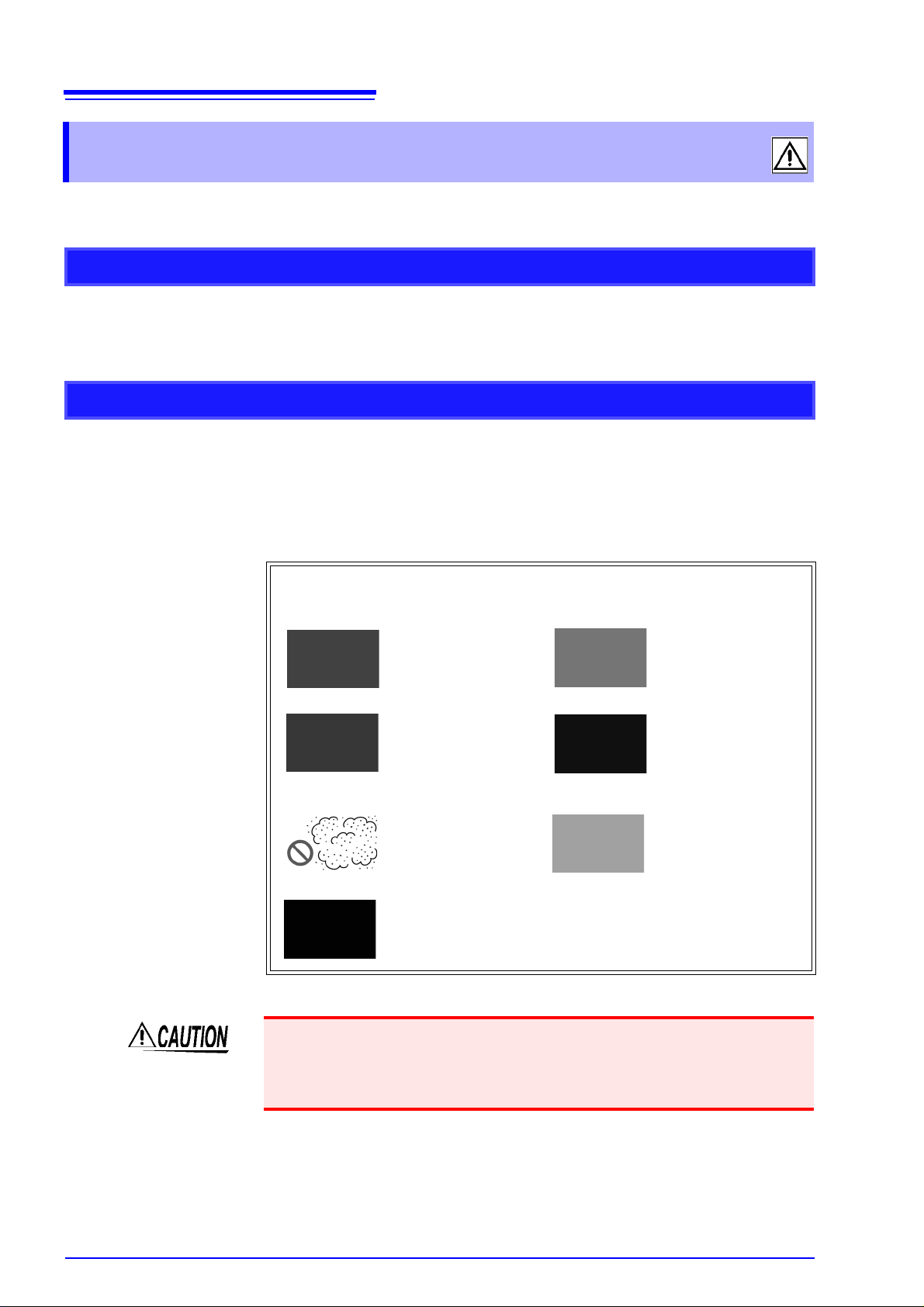
Avoid the following locations that could cause an accident or damage
to the instrument.
Exposed to direct
sunlight
Exposed to high tem-
perature
In the presence of cor-
rosive or explosive
gases
Exposed to water, oil,
other chemicals, or
solvents
Exposed to high
humidity or conden-
sation
Exposed to strong
electromagnetic fields
Near electromagnetic
radiators
Exposed to high lev-
els of particulate dust
Near electromagnetic
radiators (e.g., high-
frequency induction
heating systems and IH
cooking utensils)
Subject to vibration
The instrument’s sensor unit consists of precision optical components. Dropping
the sensor unit or subjecting it to mechanical shock may damage it. Optical com-
ponents inside the sensor unit may fall out of alignment if the unit is dropped or
subjected to mechanical shock, affecting measured values.

Operating Precautions
5
Installation
Attaching rubber feet to the main unit
• The instrument ships with four rubber feet for use with the main unit. Attach
the rubber feet to the bottom of the instrument as necessary.
• When attaching the rubber feet to the base of the main unit, refer to the follow-
ing diagram for a rough indication of how the feet should be positioned.
• Do not slant the instrument or place it on top of an uneven surface. Dropping or
knocking down the instrument can cause injury or damage to the instrument.
• The instrument’s sensor unit consists of precision optical components. The
sensor unit should be secure mounted on a jig using the screw hole in its base.
Dropping the sensor unit or subjecting it to mechanical shock may damage it.
• When orienting the instrument’s main unit so that a part other than its base is
facing down, fix it in place so that it cannot fall. Failure to do so may cause a
fire or other malfunction in the main unit.
• The instrument is housed in a metal case and emits heat. Be sure to leave
adequate space around the instrument. Failure to do so may cause the ambi-
ent temperature to rise, affecting measured values and potentially damaging
the instrument.
Jig for securing sensor unit
(provided by customer)
Attach
rubber
feet here
Attach
rubber
feet here
Base of main unit

Operating Precautions
6
Connecting the sensor unit to an integration sphere
• When connecting the sensor unit to an integration sphere, use the included
screws to affix it to the integration sphere’s port. If the instrument is not com-
patible with the size of the integration sphere’s port, please contact HIOKI.
• Small pieces of paint may fall out of the screw holes when attaching the
screws. Remove any pieces of paint before affixing the instrument to the inte-
gration sphere.
• When connecting the sensor unit to the integration sphere, you are responsible
for providing a jig to support the sensor unit. Use the screw hole in the base of
the sensor unit to attach it securely to the jig.
Connecting
screws for con-
necting port
Jig for securing sensor unit
(provided by customer)

Operating Precautions
7
Handling the Instrument
To avoid electric shock, do not remove the instrument's cover and panel.
The internal components of the instrument carry high voltages and may
become very hot during operation.
•Do not allow the instrument to get wet, and do not take measurements
with wet hands. This may cause an electric shock.
•Do not use the instrument where it may be exposed to corrosive or com-
bustible gases. The instrument/ device/ product may be damaged or
cause an explosion.
• To avoid damage to the instrument, protect it from physical shock when trans-
porting and handling. Be especially careful to avoid physical shock from drop-
ping.
• The instrument’s sensor unit consists of precision optical components. Drop-
ping the sensor unit or subjecting it to mechanical shock may cause operation
to diverge from its accuracy specifications. An inspection is necessary in the
event the instrument is subject to mechanical shock.
• The upper limit of the instrument’s measurement range is 100,000 lx.
Do not expose the instrument to light in excess of 100,000 lx. Doing so may
cause degradation of the sensor unit’s internal optical components.
• This instrument is designed for use indoors. It can be operated at tempera-
tures between 5 and 35°C without degrading safety.
• Do not store or use the instrument where it could be exposed to direct sunlight,
high temperature or humidity, or condensation. Under such conditions, the
instrument may be damaged and insulation may deteriorate so that it no longer
meets specifications.
• This instrument is not designed to be entirely water- or dust-proof. Do not use
it in an especially dusty environment, nor where it might be splashed with liq-
uid. This may cause damage.
• This instrument is not drip-proof. Water droplets on the connector may result in
malfunctions.
• Do not allow the instrument to get wet, and do not take measurements with wet
hands. This may cause an electric shock.
• Do not use the instrument near a source of strong electromagnetic radiation, or
near a highly electrically charged object. These may cause a malfunction.
• Do not use the instrument in the vicinity of induction heating equipment (high-
frequency induction heating equipment, induction heating cooktops, etc.).
Doing so may damage the instrument or cause fire.
Correct measurement may be impossible in the presence of strong magnetic
fields, such as near transformers and high-current conductors, or in the pres-
ence of strong electromagnetic fields such as near radio transmitters.
Altri manuali per TM6101
1
Indice
Altri manuali Hioki Strumento di misura

Hioki
Hioki RM3544 Manuale utente

Hioki
Hioki 3506-10 Manuale utente

Hioki
Hioki 3196 Manuale utente

Hioki
Hioki HITESTER 3184 Manuale utente

Hioki
Hioki CM4375 Manuale utente

Hioki
Hioki FT3424 Manuale utente

Hioki
Hioki PW3360-21 Manuale utente

Hioki
Hioki IM3523A Manuale utente

Hioki
Hioki SP7001 Manuale utente

Hioki
Hioki MR8875 Manuale utente

Hioki
Hioki DM7275 Series Manuale utente

Hioki
Hioki CT7631 Manuale utente

Hioki
Hioki 3284 HiTester Manuale utente

Hioki
Hioki CM4141 Manuale utente

Hioki
Hioki IM7580A Series Manuale utente

Hioki
Hioki 3293-50 Manuale utente

Hioki
Hioki LR8450 Manuale utente

Hioki
Hioki CM4371-50 Manuale utente

Hioki
Hioki RM3545A-1 Guida utente

Hioki
Hioki 3155-01 Manuale utente


