IS Technologies SLM800S Manuale utente

Ultrasonic Level Meter SLM800S/1200S
(USER’S MANUAL)
IS Technologies Co., Ltd.

2
SLM800S/1200S
March 2003
COPYRIGHT
© IS Technologies Co., Ltd. All rights reserved. No part of this publication may be reproduced, transmitted, transcribed,
stored in a retrieval system, or translated into any language in any form without the written permission of IS Technologies
Co., Ltd.
WARRANTY AND LIABILITY
IS Technologies Co., Ltd. guarantees for a period of 1 year from the date of delivery that it will either exchange or repair any
part of this product returned to IS Technologies Co., Ltd. if it is found to be defective in material or workmanship, subject to
the defect not being due to unfair wear and tear, misuse, modification or alteration, accident, misapplication or negligence.
DISCLAIMER
IS Technologies neither gives nor implies any process guarantee for this product, and shall have no liability in respect of any
loss, injury or damage whatsoever arising out of the application or use of any product or circuit described herein.
Every effort has been made to ensure accuracy of this documentation, but IS Technologies cannot be held liable for any errors.
TECHNICAL ENQUIRIES
Please contact IS Technologies Co., Ltd. for technical support.
IS Technologies Co., Ltd.
203/504 Buchon Techno Park, 192, Yakdae Dong, Wonmi Gu, Buchon City Kyungki, Korea
Tel: 82-32-621 2606 Fax: 82-32-621 2612
Web Site: http://www.sondar.com

3
Contents
Chapter 1 Product Specification….......................................................................................................................................4
Chapter 2 Installation............................................................................................................................................................5
Power Supply Requirements ................................................................................................................................................5
Dimensions ............................................................................................................................................................................6
Terminal Connection .............................................................................................................................................................6
Outdoor and Open Vessel Application……………………………………………………………………………………….8
Closed Vessel Application……………………………………………………………………………………………………..8
Stand Pipe Application…………………………………………………………………………………………………………8
Chapter 3 How To Use Controller ......................................................................................................................................9
Operating the Controller ........................................................................................................................................................9
Chapter 4 Menu Guide.......................................................................................................................................................11
Application Menu Options ...................................................................................................................................................11
Process Menu Options........................................................................................................................................................13
Compensation Menu Options .............................................................................................................................................16
Chapter 5 Digital Communication......................................................................................................................................19
Chapter6 Trouble Shooting…………………………………………………………………………………………………20
Menu Option Record…………………………………………………………………………………………………………….21

4
Chapter 1 Product Specification
Product Composition
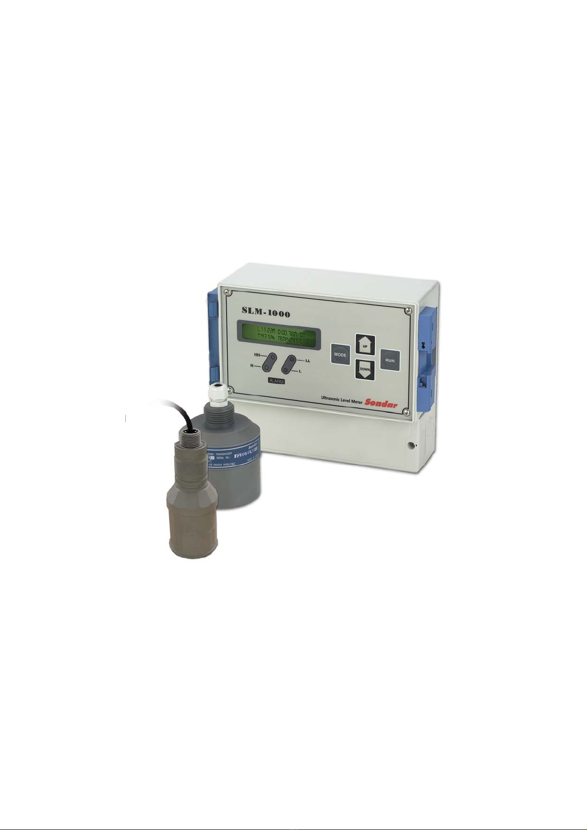
SLM800S : SLM1000(CONTROLLER) + XDS800(SENSOR)
SLM1200S : SLM1000(CONTROLLER) + XDS1200(SENSOR)
Physical
Dimensions Controller 240 (width). x 185 (height) mm = SLM1000(Controller)
Sensor 67 (dia) x160 (height) mm = XDS800
88 (dia) x 100 (height) mm = XDS1200
Mounting 3/4”NPT(XDS800), 1”NPT(XDS1200)
Weight Nominal 3.0 kg
Sensor material PP(XDS800), PVC(XDS1200), STS(XDS800-Option)
Environmental
IPRating(electronicshousing) IP65
Max. & Min. temperature (electronics) -20 ºC to +60 ºC
Performance
Accuracy 0.35% of the measured range
Resolution 1mm
Max. range Liquids8m/12m
Min. range 0.35meters / 0.50 meters
Beam Angle 12o at -3dB.
Damping Rate Adjustable from 0.1m/min to 100m/min
Temperature Compensation Fully compensated via integral temperature sensor over entire operational span
Explosion Proof EEX d II T6
Outputs
Analogue output 4-20mA into Max 900Ω(user adjustable) Fault condition Alarm 3.8mA
or 21mA user selectable.
Display 2 Line 40 Characters LCD
Programming
On-board programming via 4 tactile push button keys
Supply
Power supply AC 90 ~ 260V, DC 12/24V

5
Chapter 2 Installation
Power Supply Requirements
The SLM800S/1200S operate from an AC supply of 90 –260V or DC 12/24V.
All electronic products are susceptible to electrostatic shock, so follow proper grounding
procedures during installation.
The construction of the SLM800S/1200S can be mounted easily using the thread (3/4” NPT, 1”NPT ).
When choosing a location to mount the XDS800/1200(Sensor), bear in mind the following:
•For easy access to the LCD display and programming buttons mount it where it is easily
accessible.
•The ultrasonic signal path should be free of falling material and obstructions such as pipes,
beams etc.
•The XDS800/1200(Sensor) should be mounted at least 35/50cm above the maximum level
of the material and be perpendicular to the surface.
•The mounting surface should be vibration-free.
•The ambient temperature of the sensor is between -20ºC and 70ºC.
•There should be no high voltage cables or electrical inverters close by.
•Do not use any metal substances when installing
(Please use the PVC nut & flange supplied as option)
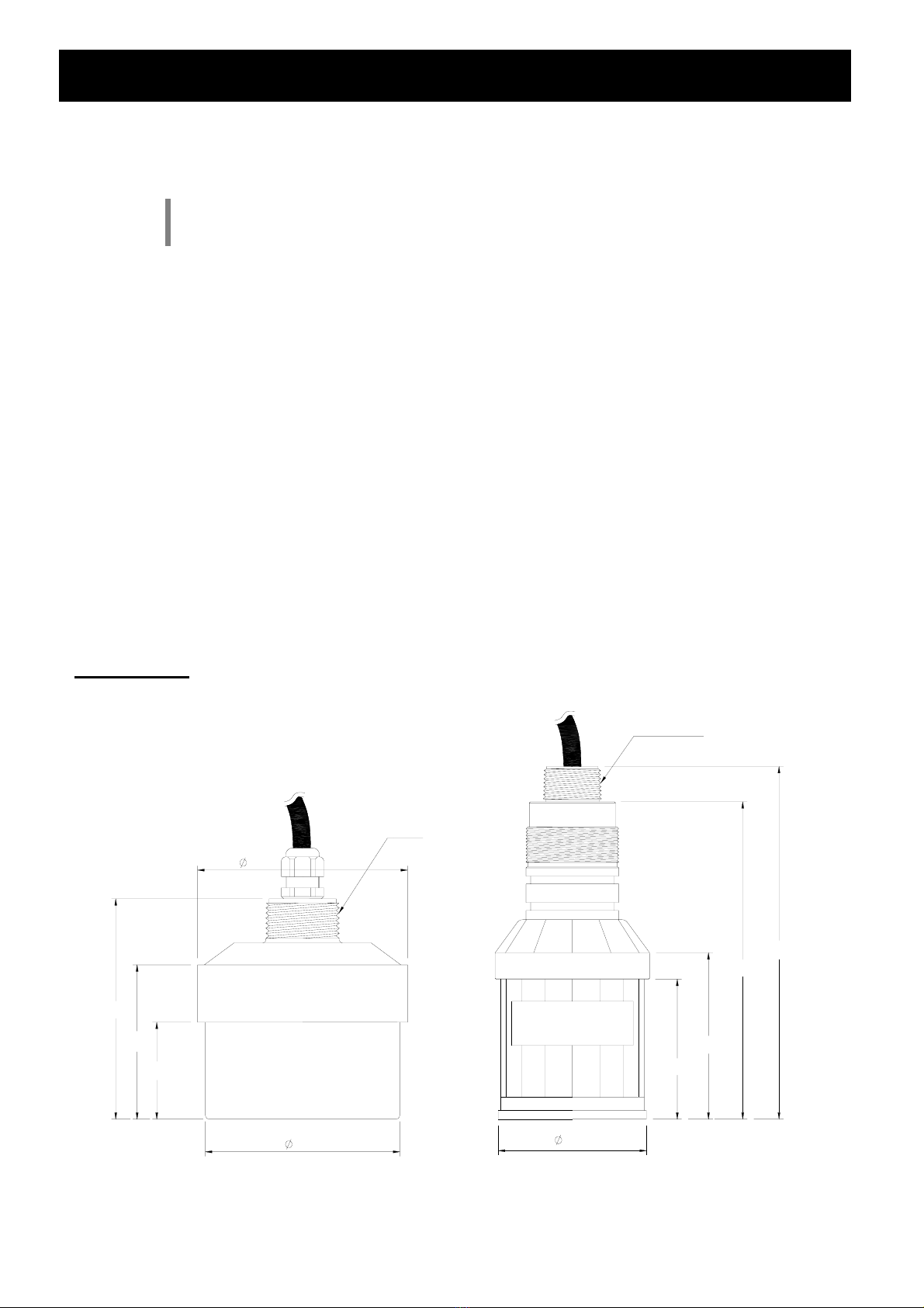
Dimensions
XDS800/1200
70
100
44
95
1" PF
88
75.5
63.5
160
144
3/4" NPT
67

6
SLM1000
SLM-1000
HH
H
ALARM
L
LL
MODE
Sondar
DOWN
UP
RUN
Ultrasonic Level Meter
240
213
185
240
145
15
12560
(185)
198
(107)
60
47
145 15
198
213
Terminal Connection
26 terminals are aligned inside the terminal box.
Input & Output Terminals
SEN+
SEN-
IOUT
RTH
IRTN
TX
L_COM
L_NOLL_NO
GND
RX
LL_COM
LL_NC
H_COM
H_NCL_NC H_NO HH_NO
HH_COM
HH_NC
ER_COM
ER_NO ER_NC
LN

7
Function
Terminal Function Note
SEN+ Connect to positive wire(red) of ultrasonic sensor
SEN- Connect to shield wire(blue) of ultrasonic sensor
RTH This terminal is only used at factory
IOUT 4~20mA current output Maximum :900Ω
IRTN Current output return
TX RS232C interface in use, connect to reception part
RS485 interface in use, connect to Y OPTION
RX RS232C interface in use, connect to transmission part
RS485 interface in use, connect to Z OPTION
GND GROUND, RX, TX
LL_NO Lower limit relay point, OFF with LL_COM together in operation
LL_COM Lower limit relay point, OFF with LL_NO together in operation
LL_NC Lower limit relay point, OFF with LL_COM together out of operation
L_NO Lower Alarm relay point, OFF with L_COM together in operation
L_COM Lower Alarm relay point, OFF with L_NO together in operation
L_NC Lower Alarm relay point, OFF with L_COM together out of operation
H_NO Upper Alarm relay point, OFF with H_COM together in operation
H_COM Upper Alarm relay point, OFF with H_NO together in operation
H_NC Upper Alarm relay point, OFF with H_COM together out of operation
HH_NO Upper limit relay point, OFF with HH_COM together in operation
HH_COM Upper limit relay point, OFF with HH_NO together in operation
HH_NC Upper limit relay point, OFF with HH_COM together out of operation
ER_NO Error relay point, OFF with ER_COM together in operation
ER_COM Error relay point, OFF with ER_NO together in operation
ER_NC Error relay point, OFF with ER_COM together out of operation
L Connect to line of AC power
N Connect to neutral of AC power
Quantity of cables gland provided and the cable thickness
Model Quantity Thickness(ømm)
PG9 1 4~8
PG11 4 5~10
PG13.5 1 6~12

8
Outdoor and Open Vessel Installation
The XDS800S/1200S can be simply mounted on a bracket, suitable for the application and secured
using the thread located at the top of the transducer (3/4”NPT, 1” NPT).
Care should be taken to ensure that the XDS800/1200 are not installed in direct sunlight, in order to
avoid errors in the measurement of ambient temperature.
Attention should also be taken, when mounting the unit, to ensure that strong windy conditions are
avoided, wherever possible, to prevent abnormal operation.
Closed Vessel Installation
The XDS800/1200 can be simply screwed into a flange and secured using the thread located at the
top of the transducer (3/4”NPT, 1”NPT).
Where possible use a flange made of a synthetic material such as PVC, to avoid vibration
Place a rubber gasket between the flange and the connection to the vessel to avoid vibration.
Stand Pipe Installation
When mounting the XDS800/1200 to a standpipe care should be taken to ensure that the
standpipe is of sufficient dia with reference to its length, see the table below for details:
When using a standpipe, fixed to the top of a vessel, ensure that the open end of the standpipe is
clear of any obstructions such as weld seams, gaskets etc. in order to avoid unwanted signal
returns.
If using standpipes, which extend into the vessel, beyond the blanking distance, but not as far as
the empty level, then the open end of the standpipe should be cut to an angle of 45o.
Maximum Length(mm)D
[mm] XDS-800 XDS-1200
80 300 305
100 380 380
150 570 570
200 760 760

9
Chapter 3 How To Use Controller
Operating the Controller
Display Window
SLM1000 is designed to display various data at the same time by adopting 40 letter LCD.
The display below shows an example of a normal operation of SLM1200S.
Conditions : The distance between the sensor and bottom of the tank : 12m
Current liquid level : 10m
1) L : 10.00 m : shows the current liquid level 10m
2) D : 2.00 m : shows the distance between the sensor and liquid level.
3) M : 86.9% : Percentage of the level
4) TEMP : Temperature around the sensor.
5) D : Indication of normal operation, shows returning echoes are well detected.
6) T : Indication of normal operation, shows tracking of returning echoes is okay.
7) S : No appearance under normal operation, but appears during abnormal operation
such as abrupt level change. Searching for the returning echoes.
Setting Buttons
MODE
DOWN
UP
RUN
1) MODE Button : Used for setting data and moving to another mode.
L : 10. 00 m D : 2 . 00 m D T
M : 86 . 9 % TEMP : +24 . 5 °C

10
2) UP Button : Used for increasing the value.
3) DOWN Button : Used for decreasing the value.
4) RUN Button : Used for starting measurement.
Alarm Display
H
HH
L
LL
1)HH LED Lamp : Lighted in case of upper limit operated
2)H LED Lamp : Lighted in case of upper alarm operated
3)L LED Lamp : Lighted in case of lower alarm operated
4)LL LED Lamp : Lighted in case of lower limit operated
Questo manuale è adatto per i seguenti modelli
1
Indice
Altri manuali IS Technologies Strumento di misura