Madison MD4814 Manuale utente
Madison Company
27 Business Park Dr
Branford CT 06405 USA
Tel (203) 488-4477 www.madisonco.com
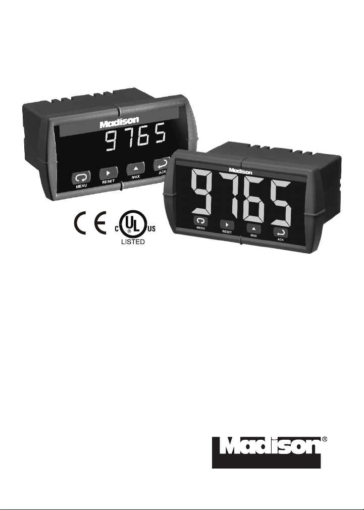
MD4814 & MD4814-X2
Process Meters
Instruction Manual
•Accepts Current, Voltage, TC, & RTD Inputs
•4 Digit Display, 0.56" (14 mm) or 1.20" (31 mm)
•Linear or Square Root with Low-Flow Cutoff
•Operating temperature range of between -40°C and 65°C
•Maximum/Minimum Display
•Type 4X, NEMA 4X, IP65 Front
•Universal Power Supply 85-265 VAC
•Two Relays Option
•24 VDC Transmitter Power Supply Option
•USB, RS-232, & RS-485
Serial Communication Adapters Options
•Free Modbus
®
RTU Protocol
•Copy Meter Settings to Other Meters
•Free MeterView
®
Software - Configuration & Data Acquisition

MD4814 Universal Input Meter Instruction Manual
2
Disclaimer
The information contained in this document is subject to change
without notice. Madison makes no representations or warranties with
respect to the contents hereof, and specifically disclaims any implied
warranties of merchantability or fitness for a particular purpose.
Registered Trademarks
Modbus®is a registered trademark of Schneider Automation Inc. All
other trademarks mentioned in this document are the property of
their respective owners.
© 2015 Madison Company. All rights reserved.
INTRODUCTION
The MD4814 is a multipurpose, easy to use digital meter. It accepts
current, voltage, thermocouple, and RTD signals. The four front panel
buttons make the setup and programming an easy task.
The isolated 24 VDC transmitter power (optional) can be used to power
the input transmitter, the 4-20 mA output, or other devices.
The two relays (optional) can be used for alarm indication or process control
applications, such as pump alternation control.
The 4-20 mA isolated output and the Modbus RTU serial communication
options make the MD4814 an excellent addition to any system.

MD4814 Universal Input Meter Instruction Manual
3
ORDERING INFORMATION
MD4814
85-265 VAC Model Options Installed
MD4814-110-00 24 V transmitter supply
MD4814-110-02 2 relays & 24 V transmitter supply
12-36 VDC Model Options Installed
MD4814-012-00-4 4-20 mA Output
MD4814-X2
85-265 VAC Model Options Installed
MD4814-110-X2 2 relays & 24 V transmitter supply
Accessories
Model Description
PDA7232 RS-232 serial adapter with PDA7420 included
PDA7420 MD4814 meter copy cable, 7' (2.1 m)
PDA7422 RS-485 serial adapter with PDA7420 included
PDA7485-I RS-232 to RS-485 isolated converter
PDA7485-N RS-232 to RS-485 non-isolated converter
PDA8485-I USB to RS-422/485 isolated converter
PDA8485-N USB to RS-422/485 non-isolated converter
PDA8006 USB Serial Adapter
MeterView®Free MeterView®software download at
www.madisonco.com

MD4814 Universal Input Meter Instruction Manual
4
Table of Contents
INTRODUCTION ------------------------------------------------------------ 2
ORDERING INFORMATION --------------------------------------------- 3
SPECIFICATIONS---------------------------------------------------------- 7
General-------------------------------------------------------------------------------7
Process Input ----------------------------------------------------------------------8
Temperature Inputs -------------------------------------------------------------- 9
Relays Option-------------------------------------------------------------------- 10
Isolated 4-20 mA Transmitter Output ------------------------------------ 11
Serial Communications------------------------------------------------------- 11
COMPLIANCE INFORMATION ----------------------------------------12
Safety ------------------------------------------------------------------------------- 12
Electromagnetic Compatibility--------------------------------------------- 12
SAFETY INFORMATION ------------------------------------------------13
INSTALLATION ------------------------------------------------------------14
Unpacking------------------------------------------------------------------------- 14
Panel Mounting------------------------------------------------------------------ 14
Connections---------------------------------------------------------------------- 15
Connector Labeling ---------------------------------------------------------- 15
Power Connections ---------------------------------------------------------- 16
Signal Connections ---------------------------------------------------------- 16
Serial Communication ------------------------------------------------------- 20
Relays and 24 V Output Connections ----------------------------------- 20
Switching Inductive Loads-------------------------------------------------- 20
4-20 mA Output & Input Signal Connections -------------------------- 22
SETUP AND PROGRAMMING ----------------------------------------23
Front Panel Buttons and Status LED Indicators --------------------- 24
Display Functions and Messages----------------------------------------- 25
Main Menu ------------------------------------------------------------------------ 28
Setting Numeric Values ------------------------------------------------------ 28
Setting up the Meter (setu)-------------------------------------------------- 29
Setting the Input Signal (inpt) -------------------------------------------- 30
Setting the Decimal Point (dc.pt) ----------------------------------------- 31
Setting the Temperature Scale (F C) ---------------------------------- 31
Programming the Meter (prog) ------------------------------------------- 32
Scaling the Meter (scal)---------------------------------------------------- 33
Calibrating the Meter (Cal)------------------------------------------------- 35
Recalibrating Temperature Inputs (Cal) -------------------------------- 35

MD4814 Universal Input Meter Instruction Manual
5
Recalibrating Process Inputs (ICal)------------------------------------- 36
Setting the Relay Operation (rely) -------------------------------------- 37
Relay and Alarm Operation ------------------------------------------------ 41
Pump Alternation Control Operation------------------------------------- 46
Scaling the 4-20 mA Analog Output (Aout) ---------------------------- 47
Program the Sensor Break Output Value (SEbr) --------------------- 48
Analog Output when Display is Out of Range------------------------- 48
Setting up the Password (pass) ------------------------------------------- 49
Locking the Meter ------------------------------------------------------------ 49
Unlocking the Meter---------------------------------------------------------- 49
Advanced Features Menu---------------------------------------------------- 50
Advanced Features Menu & Display Messages ---------------------- 51
Offset Adjustment (Adj)----------------------------------------------------- 53
Noise Filter (fltr)------------------------------------------------------------ 53
Noise Filter Bypass (byps) ------------------------------------------------- 54
Serial Communications (serl) -------------------------------------------- 54
Protocol Selection Menu (Prot) ------------------------------------------ 54
Select Menu (SElc) ---------------------------------------------------------- 55
Linear or Square Root Function (linr or Sqrt) ---------------------- 55
Low-Flow Cutoff (cutF) ----------------------------------------------------- 56
Display Intensity (inty) ----------------------------------------------------- 56
Meter Copy Function (Copy) ----------------------------------------------- 57
Internal Calibration (ICal)-------------------------------------------------- 59
OPERATION ----------------------------------------------------------------62
Front Panel Buttons Operation -------------------------------------------- 62
Maximum/Minimum Readings---------------------------------------------- 63
MOUNTING DIMENSIONS ----------------------------------------------64
TROUBLESHOOTING----------------------------------------------------65
Diagnostics Menu (diag)----------------------------------------------------- 65
Determining Software Version -------------------------------------------- 65
Reset Meter to Factory Defaults ------------------------------------------- 66
Factory Defaults & User Settings ----------------------------------------- 67
Troubleshooting Tips --------------------------------------------------------- 69
QUICK INTERFACE REFERENCE GUIDE -------------------------70

MD4814 Universal Input Meter Instruction Manual
6
Table of Figures
Figure 1. Panel Cutout and Mounting............................................... 14
Figure 2. Labeling for 2 Relay, Analog Out, & 24 V Supply Model .15
Figure 3. Power Connections ............................................................16
Figure 4. Transmitter Powered by Ext. Supply or Self-Powered .... 16
Figure 5. Transmitters Powered by Internal Supply (Optional) ......17
Figure 6. Voltage Input Connections ................................................ 17
Figure 7. Thermocouple Input Connections .................................... 18
Figure 8. Three-Wire RTD Input Connections ..................................18
Figure 9. Two-Wire RTD Input Connections..................................... 19
Figure 10. Four-Wire RTD Input Connections.................................. 19
Figure 11. Relay & 24 V Output Connections................................... 20
Figure 12. AC and DC Loads Protection...........................................20
Figure 13. Low Voltage DC Loads Protection .................................. 21
Figure 14. 4-20 mA Output & Input Signal Powered by Meter ........ 22
Figure 15. 4-20 mA Output Powered Externally............................... 22
Figure 16. Meter Copy Connection ................................................... 57
Figure 17. Meter Dimensions – Side View ........................................64
Figure 18. Case Dimensions – Top View .......................................... 64

MD4814 Universal Input Meter Instruction Manual
7
SPECIFICATIONS
Except where noted all specifications apply to operation at +25°C.
General
DISPLAY MD4814: 0.56" (14 mm), MD4814-X2: 1.20" (31 mm),
Four digits (-1999 to 9999), automatic lead zero blanking.
DISPLAY INTENSITY Eight intensity levels
DISPLAY
UPDATE RATE
Process/RTD: 3.7-5/second
Thermocouple: 1.8-2.5/second
OVERRANGE Display flashes 9999
UNDERRANGE Display flashes -1999
PROGRAMMING
METHODS
Four front panel buttons, PC and MeterView®software, or
cloning using Copy function
NOISE FILTER Programmable from 2 to 199 (0 will disable filter)
RECALIBRATION All ranges are calibrated at the factory. Recalibration is
recommended at least every 12 months.
MAX/MIN
DISPLAY
Max/min readings reached by the process are stored until
reset by the user or until power to the meter is turned off.
PASSWORD Programmable password restricts modification of settings.
NON-VOLATILE
MEMORY
All programmed settings are stored in non-volatile memory
for a minimum of ten years if power is lost.
POWER
OPTIONS
85-265 VAC, 50/60 Hz
90-265 VDC, 20 W max
or 12-36 VDC, 12-24 VAC, 6 W max
See table for power consumption
(* number depends on option)
Model Watts
MD4814-110-X2 8
MD4814-100-0* 20
MD4814-012-00 6
FUSE Required fuse: UL Recognized, 5 A max, slow blow
Up to 6 meters may share one 5 A fuse
ISOLATED
TRANSMITTER
POWER SUPPLY
One transmitter power supplies (Optional)
P: 24 VDC ±10% @ 200 mA max.
NORMAL MODE
REJECTION
64 dB at 50/60 Hz
ISOLATION 4 kV input/output-to-power line
500 V input-to-output or output-to-P supplies
OVERVOLTAGE
CATEGORY
Installation Overvoltage Category II:
Local level with smaller transient overvoltages than Instal-
lation Overvoltage Category III.

MD4814 Universal Input Meter Instruction Manual
8
ENVIRONMENTAL Operating temperature range: -40 to 65°C
Storage temperature range: -40 to 85°C
Relative humidity: 0 to 90% non-condensing
CONNECTIONS Removable screw terminal blocks accept 12 to 22 AWG
wire, RJ11 for serial communication adapters
ENCLOSURE 1/8 DIN, high impact plastic, UL 94V-0, color: gray
MOUNTING 1/8 DIN panel cutout required. Two panel mounting bracket
assemblies provided
TIGHTENING
TORQUE
Screw terminal connectors: 5.0 lb-in (0.56 Nm)
OVERALL
DIMENSIONS
2.45" x 4.68" x 4.19" (62 mm x 119 mm x 106 mm)
(H x W x D)
WEIGHT 9.5 oz. (269 g) (including options)
WARRANTY 3 years parts & labor
Process Input
INPUTS Field selectable:
±20 mADC (0-20, 4-20 mA) and ±10 VDC (0-5, 1-5, 0-10 V)
ACCURACY ±0.05% of span ±1 count, square root: 10-100% FS
FUNCTION Linear or square root
LOW-FLOW CUT-
OFF
0-9999 (0 disables cutoff function)
TEMPERATURE
DRIFT
0 to 65°C ambient -40 to 0°C ambient
Current: ±0.20% FS (50 PPM/°C)
Voltage: ±0.02% FS (1.7 PPM/°C)
Current: ±0.80% FS
Voltage: ±0.06% FS
DECIMAL POINT Up to three decimal places for process inputs:
d.ddd, dd.dd, ddd.d, or dddd
CALIBRATION
RANGE
An Error message will appear if input 1 and input 2 signals
are too close together.
Input
Range
Minimum Span
Input 1 & Input 2
4-20 mA 0.40 mA
±10 V 0.20 V
INPUT
IMPEDANCE
Voltage ranges: greater than 1 MΩ
Current ranges: 50 - 100 Ω(depending on resettable fuse impedance)
INPUT
OVERLOAD
Current input protected by resettable fuse.
Fuse resets automatically after fault is removed.

MD4814 Universal Input Meter Instruction Manual
9
Temperature Inputs
INPUTS Field selectable: type J, K, T, or E thermocouples;
100 Ωplatinum RTD (0.00385 or 0.00392 curve)
RESOLUTION 1°or 0.1°for all RTD inputs. 1°for all thermocouples.
1°or 0.1°for Type T thermocouple
ACCURACY
Input Type Range Accuracy
(0 - 65 C)
Accuracy
(-40 - 0 C)
Type J -58°to 1382°F
-50°to 750°C
±2°F
±1°C
±5°F
±3°C
Type K -58°to 2300°F
-50°to 1260°C
±2°F
±1°C
±4°F
±2°C
Type T -292°to 700°F
-180°to 371°C
±2°F
±1°C
±13°F
±7°C
Type T
0.1°Res
-199.9°to 700.0°F
-180.0°to 371.0°C
±1.8°F
±1.0°C
±13°F
±7.2°C
Type E -58°to 1578°F
-50°to 870°C
±2°F
±1°C
±11°F
±6°C
100 ΩRTD -328°to 1382°F
-200°to 750°C
±1°F
±1°C
±5°F
±3°C
COLD
JUNCTION
REFERENCE
Automatic, fixed, no user calibration needed
OFFSET
ADJUSTMENT
Programmable to ±19.9°. This parameter allows the user to
apply an offset value to the temperature being displayed.
INPUT
IMPEDANCE
Greater than 100 kΩ
SENSOR BREAK
DETECTION
Open TC or RTD sensor indicated by display flashing oPEn.
All relays and alarm status LEDs go to alarm or non-alarm
state, programmable for each relay individually.
Analog output goes to the programmed sensor break value.

MD4814 Universal Input Meter Instruction Manual
10
Relays Option
RATING 2 SPDT (Form C); rated 3 A @ 30 VDC or 3 A @ 250 VAC
resistive load; 1/14 HP @ 125/250 VAC (50 watts) for induc-
tive loads
ELECTRICAL
NOISE
SUPPRESSION
A suppressor (snubber) should be connected to each relay
contact switching inductive loads to prevent
disruption to the microprocessor’s operation.
Recommended suppressor value: 0.01 µF/470 Ω, 250 VAC
(PDX6901).
DEADBAND 0-100% of full scale, user selectable
HIGH OR LOW
ALARM
User may program any alarm for high or low trip point.
RELAY
OPERATION
Automatic (non-latching)
Latching
Pump alternation control
RELAY RESET User selectable via front panel buttons or PC
Automatic reset only (non-latching)
Automatic + manual reset at any time (non-latching)
Manual reset only, at any time (latching)
Manual reset only after alarm condition has cleared (latching)
Automatic reset: Relays will automatically reset when the in-
put passes the reset point.
Manual reset: Front panel ACK button. Pressing ACK re-
sets all manually resettable relays.
TIME DELAY 0 to 199 seconds, on and off delays
Programmable and independent for each relay
FAIL-SAFE
OPERATION
Programmable
Independent for each relay
AUTO
INITIALIZATION
When power is applied to the meter, relays will reflect the
state of the input to the meter.
Fail-safe operation: relay coil is energized in non-alarm condition. In
case of power failure, relay will go to alarm state.
Questo manuale è adatto per i seguenti modelli
1
Indice


