2
Description
This document is intended to provide a detailed
description of the use and operation of the
MICRO-AIDE CSI-1 Charge Status Indicator.
The CSI-1 can be used to monitor the operational
integrity of a battery charger. Unlike most devices
designed for this purpose, the CSI-1 actually
monitors the charger’s ability to provide a charging
current. The CSI-1 uses sensitive Hall Effect
technology to measure the DC current from the
charger to the battery whenever the battery voltage
falls below a user defined limit value. Should the
charger fail to provide an adequate charging current
under these conditions the CSI-1 will immediately
indicate an alarm condition. A charger failure or
prolonged commercial power interruption will
eventually result in a significant drain on the battery.
The CSI-1 can be used to provide several hours of
advance warning that a potential problem will arise if
left unchecked.
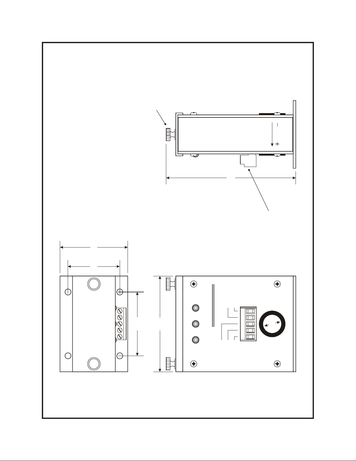
LEDs are used to indicate the status of the charging
current, battery voltage and alarm condition. A green
LED will illuminate if the current exceeds 1 Adc. A
separate green LED will illuminate if the battery
voltage exceeds a user defined limit value. If the
current and voltage fail to exceed their respective
limit values an alarm condition is reported. A red
LED and set of form C relay contacts are used to
indicate the failure. The dry contacts may be used to
signal a fault condition to an alarm reporting device
or data logger such as a MICRO-AIDE CWR-22xt
Event Recorder.
The CSI-1 is powered by the battery it monitors. Its
maximum current draw will not exceed 60 mA. It
will operate in the range from 8 to 30 Vdc. The
unit’s operating temperature range extends from
-40°C to +70°C. The CSI-1 maintains a minimum
isolation rating of 4,000 Vdc. Its use is completely
non-intrusive. Its electronic circuitry is housed in a
rugged, anodized aluminum chassis.
Figure 1 provides a three-sided view of the CSI-1.
Figure 2 illustrates the inside of the unit. The last
page of this document lists detailed specifications.
Installation
The CSI-1 may be mounted on a shelf or backboard.
It may be oriented in either a horizontal or vertical
plane. Four mounting holes at the base of the unit are
used to secure the CSI-1. It is advisable to mount the
unit in such a way that the front panel LEDs are
visible and that the cable from the charger to the
battery is conveniently routed.
A detachable connector is used to simplify the
installation procedure. Wire gauges in the range
from 12 to 22 AWG may be used. Each conductor is
secured by tightening the set screw associated with
each connector terminal. Power should not be
applied to the CSI-1 prior to completing the
installation work. The unit’s silkscreening provides a
clear depiction of the connections to be made.
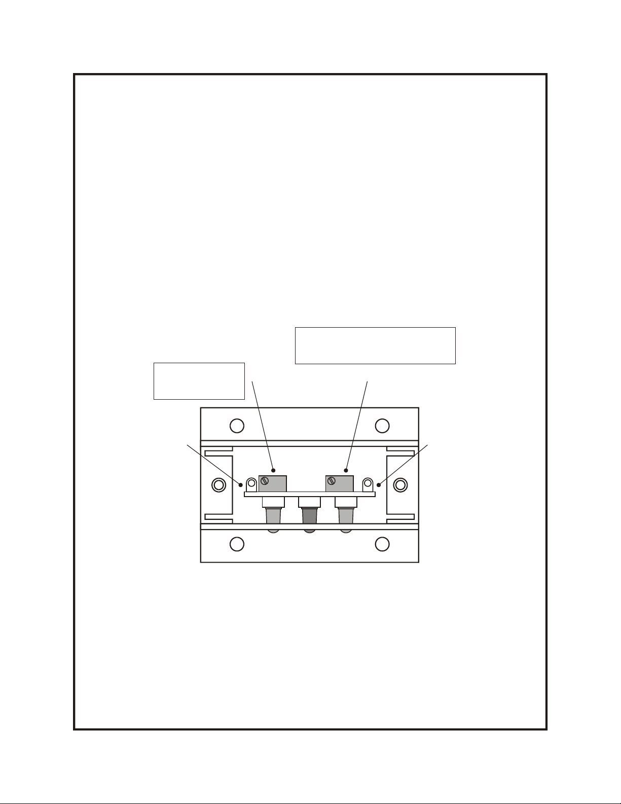
The CSI-1 draws its internal power from the battery
leads that are connected to the “B” and “N” inputs
located at the detachable screw-down connector. The
remaining three terminals are used to make
connections to the internal relay. Normally open,
normally closed and common leads are available.
Note: - The terminal labeled “NC” will be closed to
the “Com” terminal when the CSI-1 is not indicating
a failure (i.e., the voltage and current levels exceed
their respective limit values). The “NO” terminal
Designed to indicate failures in battery charging systems by
checking for inadequate charging current when the battery
volt
age is unacceptably low.
CHARGE STATUS INDICATOR