PKP DS15 Manuale utente

Instruction Manual
DS15
Plastic Variable Area Flowmeter
PKP Prozessmesstechnik GmbH
Borsigstraße 24
D-65205 Wiesbaden- ordenstadt
Tel.: ++49-(0)6122-7055-0
Fax: ++49-(0)6122-7055-50
Email: [email protected]

Safety Information
General Instructions
The device should only be operated according to the specifications in the instruction manual. The
requisite Health & Safety regulations for a given application must also be observed. This also aplies
to the use of accessories.
Proper Usage
The flowmeters model DS15 works according to the proven variable area principle. The float is
moved upward by the flowing medium and its upper edge indicates the flow rate by means of a
scale affixed onto the measuring tube.
By using a float with an integrated magnet optional alarm contacts or an analogue output transmitter
may be operated. All flowmeters have a male thread on the measuring tube and are additionally
equipped with PVC glue-in connectors. Also possible are connectors with female thread (BSP)
made of PVC, PP, PVDF, brass or st. steel.
Qualified Personnel
DS15 devices may only be installed by trained, qualified personnel who are able to mount the
devices correctly. Qualified personnel are persons, who are familiar with assembling, installation,
placing in service and operating these devices and who are suitably trained and qualified.
DS15 Instruction manual 2017-08 page 2

Mounting
Installation Position: vertical, direction of flow from bottom to top
WAR I G:
•Ensure that in case of a break in the measuring tube, no hazards result from escaping media.
•Do not use measuring tube made of PVC for gaseous media.
•Use personal protective equipment when carrying out any work on the fitting.
To avoid unstable float conditions (fluttering of float), please include in front of the flow meter and
behind it a flow-calming section of 5 to 7 x D .
Installation:
1. Ensure that measuring tube and float are clean and free of foreign matter.
2. Remove transport lock (holds the float).
3. Ensure that the float can move freely.
4. Unscrew both union nuts. Secure float (heavy) from falling
5. Push union nuts onto spigot of process pipes. Check mounting direction.
6. Weld union end of device to spigot of process pipes
7. Check fit of O-rings
8. Connect device to the process pipework. Tighten union nuts by hand only.
Performing t e ydrostatic test:
Perform hydrostatic test using neutral medium, e.g. water.
Pressurize the device, ensuring
•Test pressure < 1.5 x P ( ominal pressure)
•Test pressure < P + 5bar
•Test pressure < permissible system pressure
Check that the device is not leaking.
DS15 Instruction manual 2017-08 page 3
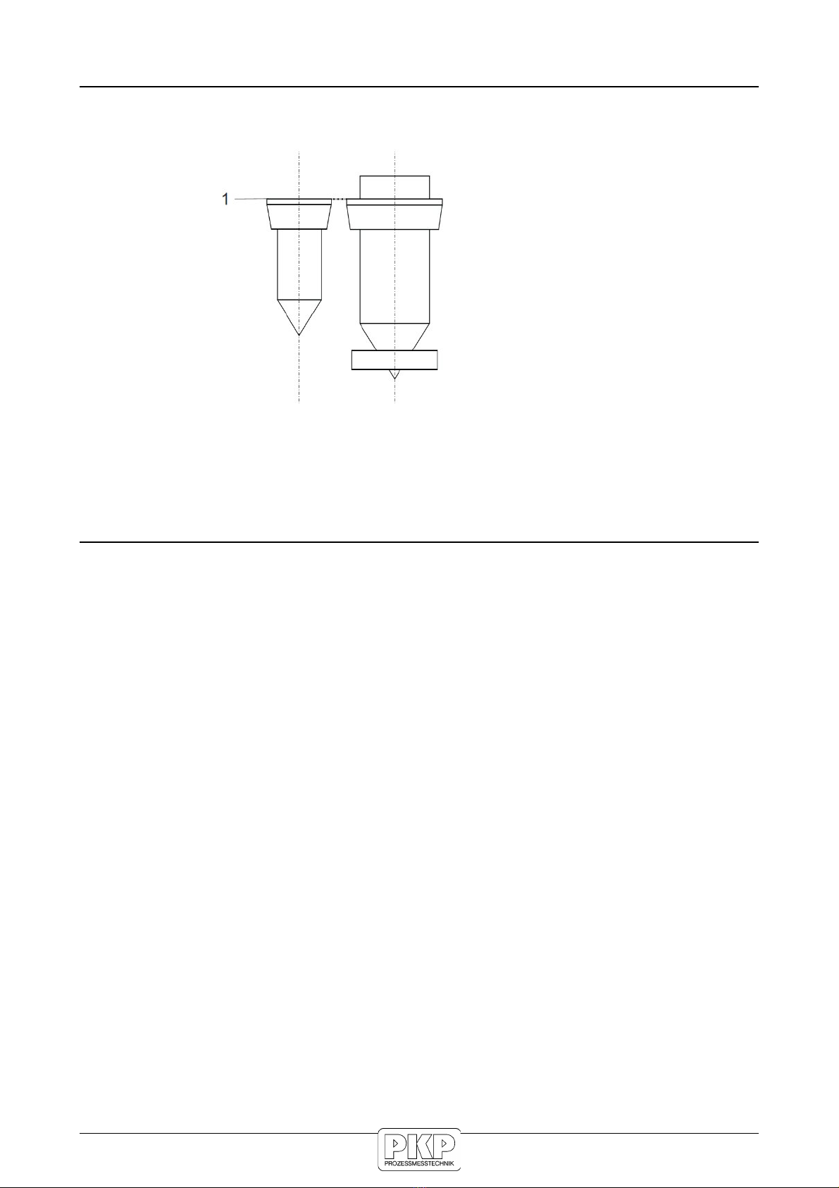
Read measurement
For the measurement range 2,500-25,000, the reading edge is below the float fixture (largest dia-
meter)
1 = Reading edge
read measurement using face (1) of float
Maintanance
1. Clean device with a damp cloth as often as necessary (depends on degree of contamination
and environmental conditions)
2. Visual and function check (every 6 months):
- ormal operating conditions unchanged
- o leaks
- Measuring tube and float for deposits or changes to surface
- float is movable
3. To clean the flowmeter, in the most cases you can flush the device with clear water. In some
cases some commercial detergents can be used.
DS15 Instruction manual 2017-08 page 4
Electrical Connection of Reed contacts
Please note: we recommend to use only shielded cables.
The polarity of the connections has no influence on the function
Operating note:
•Do not exceed the current data or the switching capacity. For this reason, always fit a contact
protection relay if a power circuit is intended.
•Prior to commissioning/first start-up it is important that the float passes the switch three
times in order to cancel out any possible monostable behaviour.
•
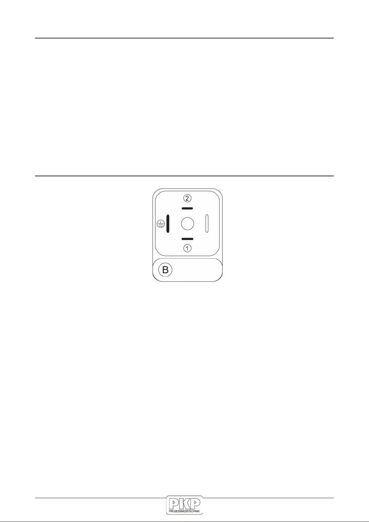
Pin Assignment
DS15 Instruction manual 2017-08 page 5
Connecting devices equipped with Reed switches
Reed switches are basically designed for small contact ratings. To connect a load with higher power
consumption it is indispensable to use a contact protection relay (e.g. our series MSR01)
If you connect directly a load to a Reed contact the following recommendations should be con-
sidered.
one of the contact rating values printed on the switching unit must not to be exceeded, even mo-
mentarily. This is valid for each of the given values individually: voltage, current, power. The Reed
contact integrated in the switching unit is very sensible to electrical overload
Danger of overload is given by the following applications:
•inductive load
•capacitive load
•lamp load
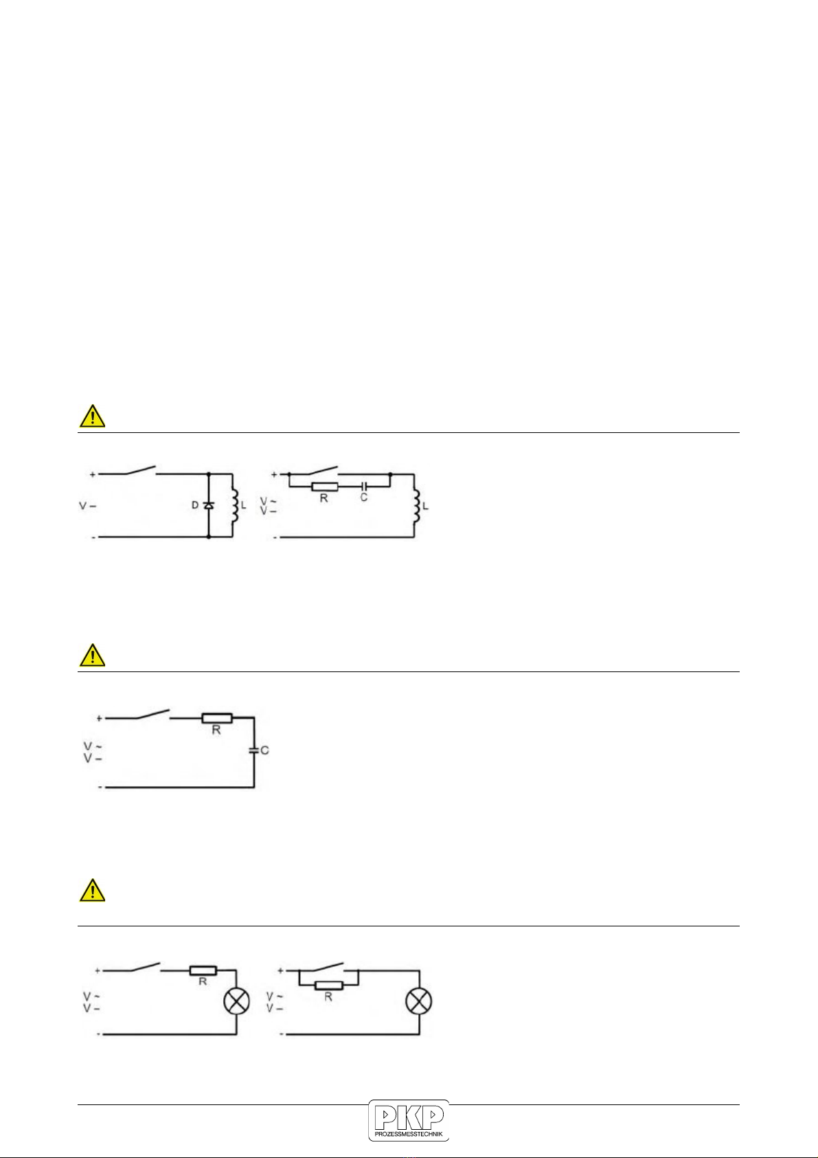
Inductive Load
Inductive loads consist e.g. of relay, contactors, solenoid valves, motors, electric engines, etc.
WAR I G: Voltage spikes at shut down (up to 10 times of nominal voltage)
Protective measures: (examples)
(Flyback diode, e.g. type 1 4007)
Capacitive Load
Capacitive loads consist e.g. of long connection cables or capacitive consumers.
WAR I G: High current spikes at switching on (this will exceed the nominal current)
Protective measures: (examples)
Limitation of current by a resistor
Lamp Load
Lamp loads consist e.g. by light bulbs, starting motors .
WAR I G: High current spikes at switching on, because the glowing spiral has low resistance
at low temperature.
Protective measures: (examples)
Limitation of current by a resistor or
preheating of the glowing spiral.
DS15 Instruction manual 2017-08 page 6
Connecting to a PLC
There is no need for protective measures by connecting the Reed switch to a PLC. The Reed con-
tacts are plated by Tunsten, Gold, and Rhodium located in a protective atmosphere. They can be dir-
ectly connected to the input terminals of a PLC without problems.
RC-Circuits as protective measures Boucherot cell, Snubber)
In practice the following values of resistor/capacitor cells give good results. evertheless, the values
given in the following tables are only recommendations for general purposes. But it cannot be guar-
anteed that for specific applications more adequate Boucherot cells may exist.
For Reed switches of 10 – 40 VA
Voltage [V] Resistance [Ohm] apacitance [nF]
230 1500 330
115 470 330
48 220 330
24 100 330
For Reed switches of 40 – 100 VA
Voltage [V] Resistance [Ohm] apacitance [nF]
230 1000 330
115 470 330
48 100 330
24 47 330
DS15 Instruction manual 2017-08 page 7

1
Flow data sensor ZE 3000
micro-processor controlled for accurate flow
measurement and evaluation
330501 - 05/06
Product description
The ZE3000 emits a 4..20 mA signal according to
industrial standards, generated in the DS15 by the
precise magnet angle detection of the magnetic
float.
Existing flowmeters (with magnetic floats) can be
easily retrofitted with the ZE3000 to electrically
signal the flow and, for instance, to further process
the values in a PLC for process control or to directly
display the flow rate.
This micro-processor controlled unit is programmed
for the DS15 concerned! This guarantees accurate
flow measurement and evaluation.
IMPORTANT: The DS15 to which the ZE3000 is to be
fitted must be known in advance!
Features:
• 2-wire technology
• 4..20mA analog output
• 8..28VDC input
• Individual programming adapted to the DFM
• 11 point calibration
• non-volatile value storage
• 0 button to compensate for the surrounding
magnetic influences
• Factory setting of the lower limit value (low-cutoff)
0..99% according to customer’s specifications
• Factory settable time lag (low-pass-filter)
0.1...2.5 sec according to customer’s specifications
• Measuring accuracy better than 0.5%
Pin 1: 8..28VDC
Pin 2: GND
Installation
Screw clamps are used to fit the ZE3000 on the
dovetail guide of the flowmeter. The plug connector
is located in the upper section.
During installation, ensure that the notch of the
ZE3000 coincides with the 50% mark on the DFM
scale.
Following this, proceed with the wiring according to
the plug assignment plan.
Plug assignment
Start-up
Once installed and the voltage is applied, press the
0 button for at least 2 sec to compensate for
surrounding magnetic influences.
During this phase ensure that the float is in its
bottom position, i.e. no flow must take place!
2
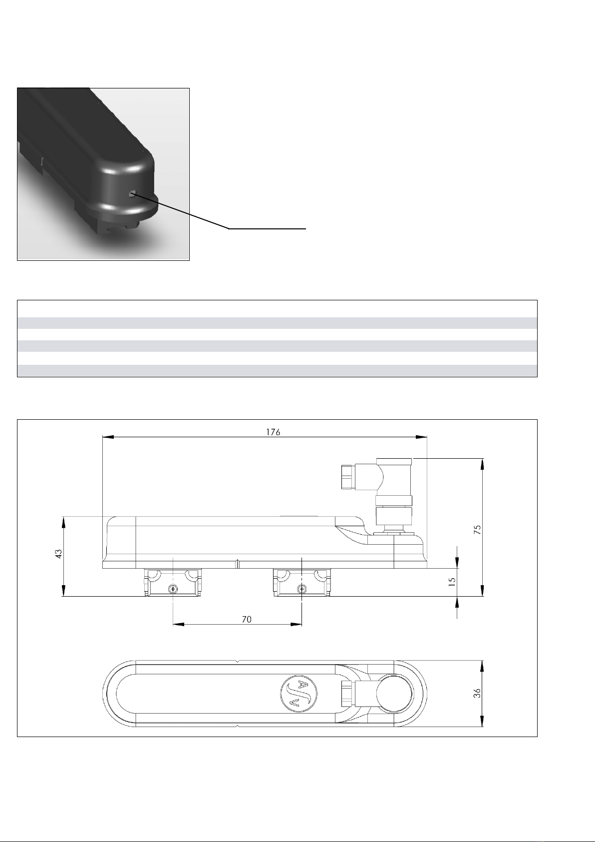
Concealed 0 button
330501 - 05/06
PARAMETERS MIN. TYPE MAX. Unit
Voltage supply 8 28 Volt DC
Output current 0% -> 100%+overrange
During normal function (pin 1 – pin2) 4.0 -> 20.1 4.0 -> 21.0 4.0 -> 22.0 mA
Ambient temperature -30 (-20) 65 (150) ºC (°F)
Dimensions
Note:
Do not actuate the button during normal operation.
Electrical/mechanical parameters
Flow Measurement and Monitoring
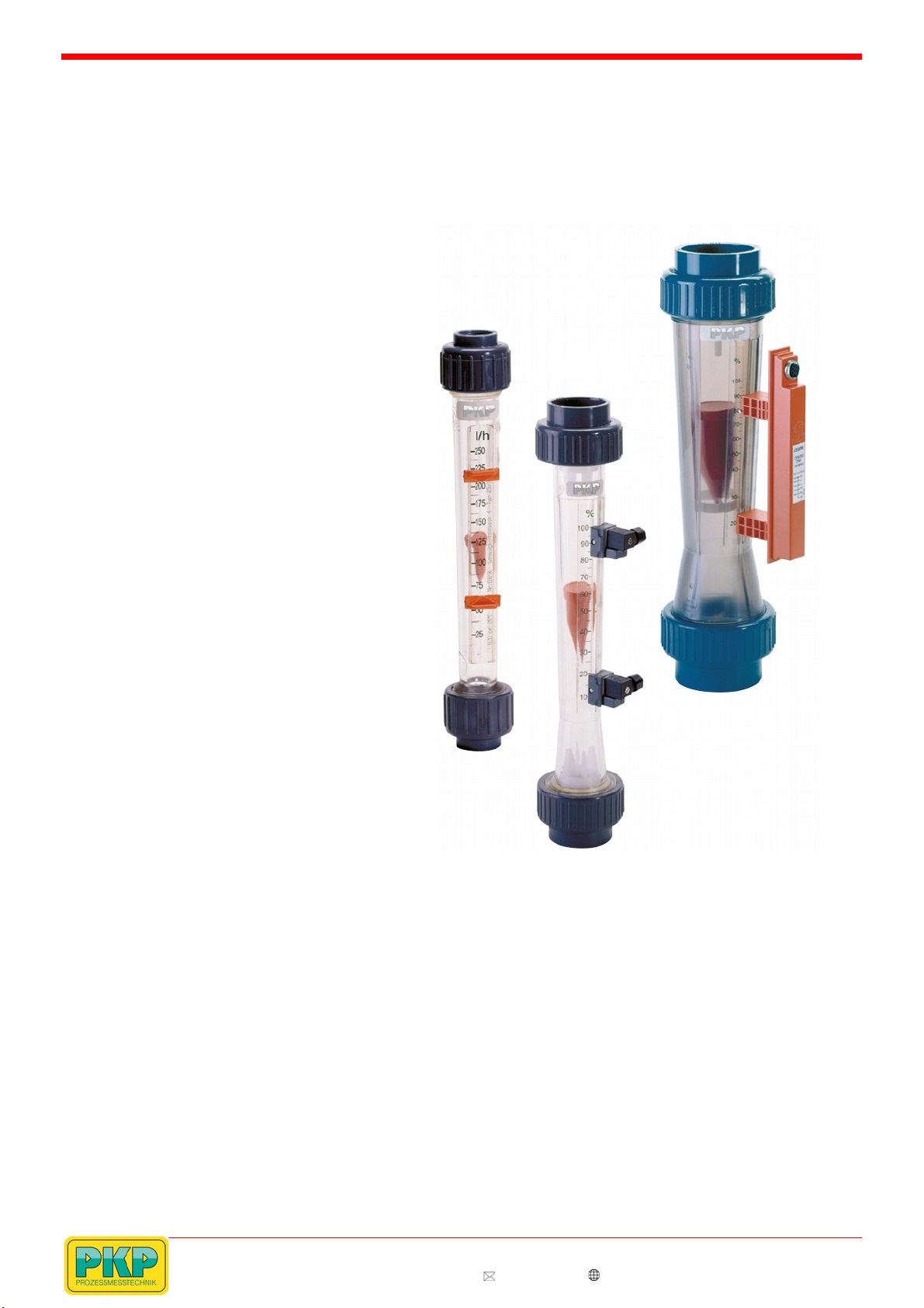
DS15
Plastic Variable Area Flowmeter
•for liquid and gaseous media
•simple and robust construction
with high reliability
•measuring tubes in PV , PA, PSU
und PVDF
•low pressure drop, simple mounting
•scale with high resolution
•alarm contacts or analogue output
optionally
•optional special scales are available
depending on medium properties
•ranges air: 0,2...1 Nm³/h - 700...2900 Nm³/h
ranges water: 3...24 l/h – 10.000-50.000 l/h
•Pmax: 10 bar, Tmax: 110 °
Description:
The flowmeters model DS15 works according to the proven
variable area principle. The float is moved upward by the flow-
ing medium and its upper edge indicates the flow rate by
means of a scale affixed onto the measuring tube. y using a
float with an integrated magnet optional alarm contacts or an
analogue output transmitter may be operated.
All flowmeters have a male thread on the measuring tube and
are additionally equipped with PVC glue-in connectors. Also
possible are connectors with female thread ( SP) made of
PVC, PP, PVDF, brass or st. steel.
Typical applications:
The variety of different materials used and the simple to
exchange measuring scales make these meters universally
suitable for most liquid and gaseous media, also suitable for
very aggressive media. Main applications are in the water
treatment industry, in waste water applications, chemical and
food industry and many more.
PKP Prozessmesstechnik GmbH
orsigstr. 24 • D-65205 Wiesbaden
S +49 (0) 6122-7055-0 • T +49 (0) 6122 7055-50
[email protected] • www.pkp.de
20181120
Indice
Altri manuali PKP Strumento di misura


