PL Engineering DX4085 Manuale utente
Moscow, 2020
version 1.02
Z-METER DX4085
USER GUIDE
PL Engineering Ltd
.

PL Engineering Ltd Z-Meter DX4085/ User Guide
page 2 of 63 ver.1.02 (2020)
Edition February 2020
Copyright
All rights reserved.
Reproduction in any manner, in whole or in part is straightly
prohibited without written permission of PL Engineering Ltd.
The information contained in this document is the subject to change
without notice.

Z-Meter DX4085/ User Guide PL Engineering Ltd
ver. 1.02 (2020) page 3 of 63
WARRANTY
PL ENGINEERING LLC warrants that the Z-Meter, if properly used
and installed, will be free from defects in material and workmanship
and will substantially conform to PL ENGINEERING’s publicly
available specification for a period of one (1) year after date of the Z-
Meter was purchased.
PL ENGINEERING LLC also provides a 3-month warranty for the
following parts and components included in the standard delivery set
of the product: the cables, program disks and documentation
If the Z-Meter fails during the warranty period PL ENGINEERING will
repair the Z-Meter or replace it or its parts.
For the warranty support a Consumer can address to the office of the
company PL ENGINEERING or its sales representative.
The product repaired or replaced in whole or in part, will have the
warranty period counted as one (1) year from initial shipment but not
less than 3 months upon shipping of repair or replacement.
TECHNICAL SUPPORT
For the technical support and repair within and after the warranty
period, please, address:
In Russia and CIS
PL Engineering Ltd.
46 Warshawskoe shosse, Moscow 115230, Russia
Tel: +7-499-678-3231
Fax: +7-499-678-3258
e-mail: info@promln.com
In Europe, the USA and other countries
TEC Microsystems GmbH.
Schwarzschildstrasse 8, Berlin 12489, Germany
Phone: +49-(0)30-6789-3314
Fax: +49-(0)30-6789-3315
e-mail: info@tec-microsystems.com

PL Engineering Ltd Z-Meter DX4085/ User Guide
page 4 of 63 ver.1.02 (2020)
CONTENTS
Warranty .......................................................................................... 3
Technical support ........................................................................... 3
1. Introduction ................................................................................. 7
2. Technical characteristics ........................................................... 9
2.1. Specifications 9
2.2. Delivery Kit 10
2.3. Design overview 11
3. Preparations for working ......................................................... 12
3.1. Charging battery 12
3.2. Connections 13
3.3. TE module connections 15
3.4. Device power ON and power OFF 15
4. Device interface ........................................................................ 16
4.1. Navigations 16
4.2. Operation modes 17
4.3. Selection of operation mode 17
4.4. Main Mode 18
4.4.1. Set of measuring parameters 19
4.4.2. Measurements 20
4.5. Measurement of AC Resistance 22
4.6. Measurement of operating voltage and temperature 24
5. Additioonal messages .............................................................. 25
6. Worwing with remote computer .............................................. 26
6.1. System Requirements 26
6.2.
Drivers Installation 26
6.3. Software Installation 27
6.4. Getting Ready 27
6.5. Measurements 28
6.5.1. Run the “Z-Meter II” software 28
6.5.2. TE Modules Connection 30

Z-Meter DX4085/ User Guide PL Engineering Ltd
ver. 1.02 (2020) page 5 of 63
6.5.3. Make the pre-sets for measurements 30
6.5.4. Measurements 32
6.5.5. Measurement results 33
7. Software ..................................................................................... 35
7.1. Introduction 35
7.2. Main Window 35
7.2.1. Menu Bar 36
7.2.2. Reference Bar 36
7.2.3. Functional Fields 37
7.3. Measurement Presets 39
7.3.1. Temperature Setting 39
7.3.2. TE Module Type 40
7.3.3. Correction Coefficients 41
7.3.4. Package Thermal Resistance 41
7.4. Measurement Procedure and Notes 42
7.5. History 44
7.5.1. File 44
7.5.2. Options 45
7.5.3. Report 45
7.6. TE Modules Database Update 46
8. Maintenance ............................................................................. 48
9. Appendix 1. theoretical groundings ....................................... 50
9.1. Time Constant 50
9.2. Interpolation Results 51
9.3. Figure-of-Merit Z 53
9.3.1. Single-stage TE Module 𝒁 53
9.3.2. Two-stage TE Module 𝒁 55
9.3.3. Alternative Correction 57
10. Appendinx 2. Measuring Processes ................................ 57
10.1. AC Resistance 57
10.2. The 𝑼 and 𝑼𝜶 Telemetry 59
10.3. Voltages for Testing 𝒁 59

PL Engineering Ltd Z-Meter DX4085/ User Guide
page 6 of 63 ver.1.02 (2020)

Z-Meter DX4085/ User Guide PL Engineering Ltd
ver. 1.02 (2020) page 7 of 63
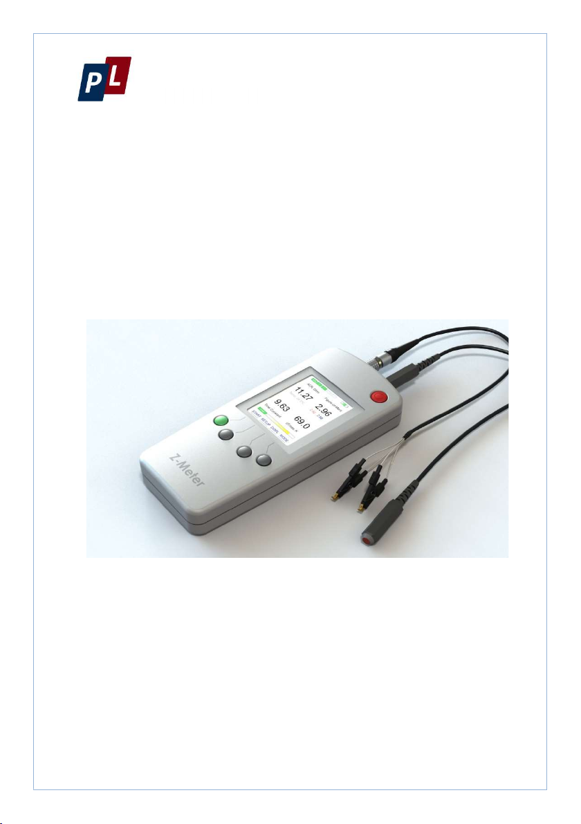
1. INTRODUCTION
The portable Z-Meter
provides measurement
of performance and
operational operating
parameters of
thermoelectric (TE)
modules. It can
measure operation and
performance of
thermoelectric cooling
modules, thermoelectric generators, and thermoelectric sensors.
The performance parameters are the following:
AC Resistance (𝑅),
Figure-of-Merit (𝑍),
Time Constant (
),
Maximum Temperature Difference (∆𝑇).
Maximal temperature difference ∆𝑇 only for single stage TECs.
Because of direct correlation with Figure of Merit is calculated within Harman
method approximations.
Additionally new functionality of this device in the family of Z-meters –
measurement of operating parameters of TECs:
Operating voltage (𝑈),
Working temperature (𝑇 or 𝑇 ).
Measurements of temperature can be used for evaluation of cooling
temperature of working TEC (𝑇) if thermal sensor is placed on TEC
cold side. Or to measure ambient temperature (𝑇)of performance
measurements – if to place near TEC.
The Z-Meter provides testing of various types of single- and two-
stage TE modules. It is possible to evaluate quality of more-stage TE
modules by the measurement of electrical resistance.
The parameters are measured at the ambient temperature 𝑇. The Z-
Meter provides recalculation of 𝑅 and ∆𝑇 to another temperature
value from the Ta vicinity.
PL Engineering Ltd Z-Meter DX4085/ User Guide
page 8 of 63 ver.1.02 (2020)
With the device it is also possible to test thermoelectric generators
and sensors: voltage at thermoelectric generator (TEG) provided by
temperature difference; response of thermoelectric heat flux sensor
ADVANTAGES
Express testing
performance of single stage
and multi-stage
thermoelectric modules.
Testing performance of TE
modules integrated into
optoelectronic devices
(photodetectors, lasers
etc.).
Operating parameters
measurements.
Compatible with other Z-
Meters of PL Engineering
Devices Family.
FEATURES
.Portable device. Metal
housing.
Measurement at direct and
reversed current.
Results normalization to
standard temperatures.
Low power consumption.
Long autonomous
operation.

Z-Meter DX4085/ User Guide PL Engineering Ltd
ver. 1.02 (2020) page 9 of 63
2. TECHNICAL CHARACTERISTICS
2.1. Specifications
Parameters U
nits Values
Electrical Resistance
𝑅
Range
O
hm
0.1...100
Accuracy
%
0.6 (but>0.01Ohm)
Repeatability
%
0.3
Figure-of-Merit
𝑍
Range 1
0-3/K
1...3
Accuracy
%
1.5
Repeatability
%
0.4
Time Constant
𝜏
Range s
1...100
Accuracy
%
1.5
Repeatability
%
1
Voltage (DC)
Range V
-20…+20
Accuracy V
0.02
Temperature Sensor
Range °
С
-40...+85
Accuracy °
С
±0.25 (typical)
±1 (maximum)
+0.05 (typical) lifetime drift
Repeatability °
C
±0.06
Power Supply
Build-in battery Li-
ion
V
3.7 (2050mAh)
Power Supply
PL Engineering Ltd Z-Meter DX4085/ User Guide
page 10 of 63 ver.1.02 (2020)
Parameters U
nits Values
AC Voltage V
110...240
Frequency H
z 50/60
Voltage DC
V
5
Power (max)
W
5
Operational Conditions
Temperature range °
С
+15...+35
Humidity
%
0...95
Storage
Temperatures range °C -20…+60
Humidity % 5…95
Mechanical Parameters
General Unit
Dimensions
m
m
70х160х21
Mass g
280
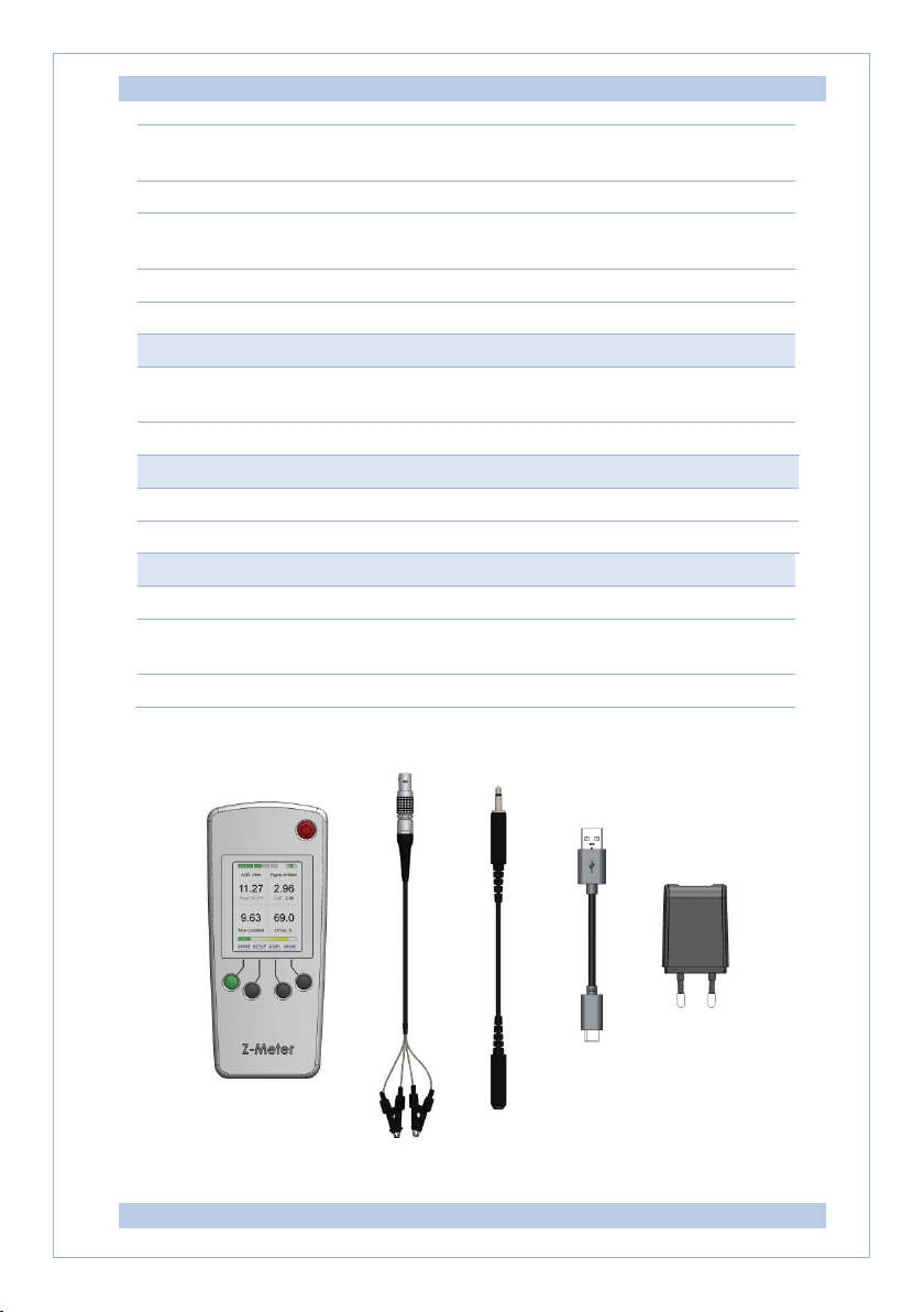
2.2. Delivery Kit
Indice
Altri manuali PL Engineering Strumento di misura


