Pocket NC V2-50DA Manuale utente

Getting Started with the
Pocket NC V2-50DA
1

TABLE OF CONTENTS
TABLE OF CONTENTS 2
Revision History 2
Introduction 2
Safety 3
Maintenance 3
Getting Started 4
Removing Shipping Bolts 4
Enclosure Installation 6
Connecting the Air Supply 9
Installing or Changing the Tool to Cut the Aligner 11
Turning on the Machine for the First Time 11
Measuring Tool Offset (telling the machine where the end of the tool is) 14
Shutdown of the Machine 16
Summary 16
Revision History
First Release: August 2019 (KN)
Introduction
Welcome to your Pocket NC V2-50DA. This tutorial goes over information on how to setup and
run the Pocket NC V2-50DA for the first time. This includes:
- Removing the shipping bolts
- Installing the machine into the enclosure
- Setting up the air supply to the spindle
- Installing a tool
- Running the machine for the first time
There are a number of videos that will also demonstrate portions of this tutorial which are
referenced.
2

Safety
The spindle moves at a very high RPM and can hurt you if you contact it while it is moving. The
motion of the spindle can be difficult to detect and it does take a few seconds to spin down after
it has been commanded to stop. It is important to be extra cautious around the tool and spindle.
Always double check that the tool is not spinning before removing your part or approaching the
machine.
Maintenance
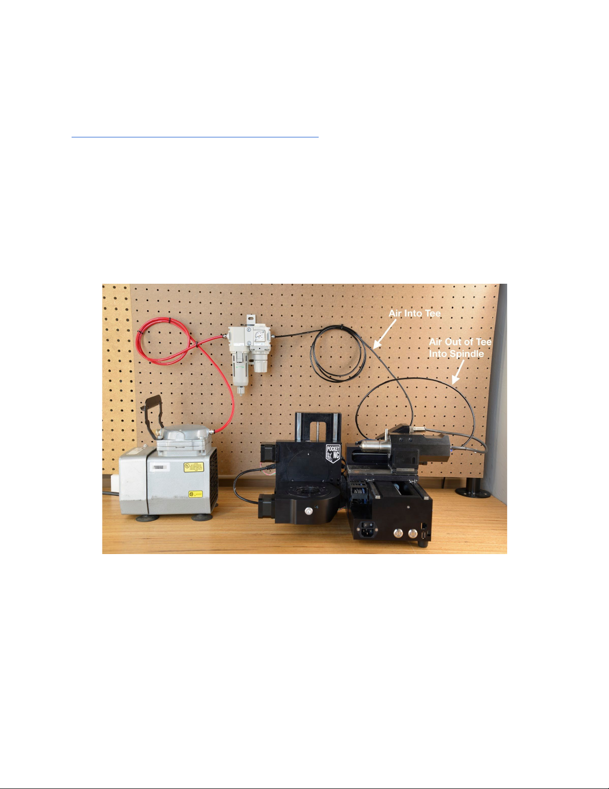
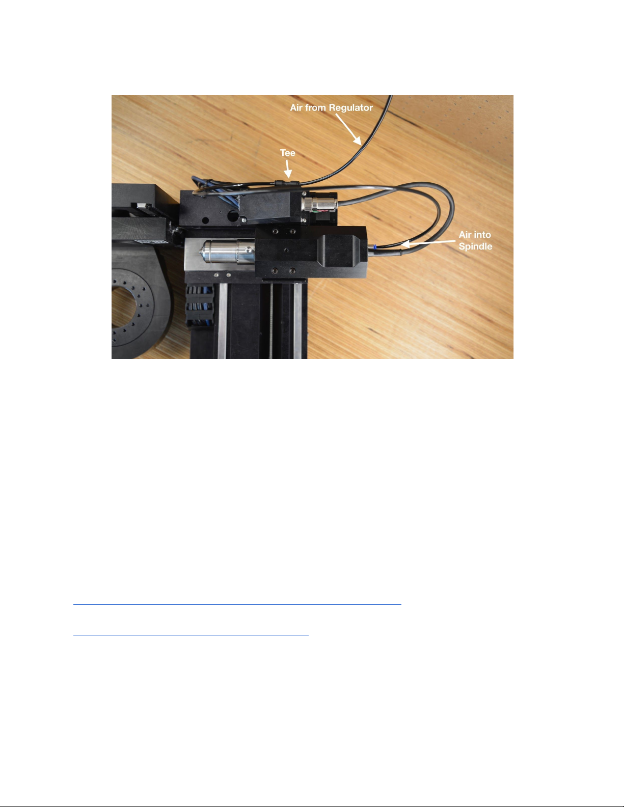
Air- Air must be attached to run the spindle, the software will not allow you to run the machine
without air hooked up and turned on to a certain pressure (0.2MPa or about 30 psi).
Warm-up- The spindle requires warming up after periods of disuse. On the user interface,
there is a “Warm-Up” button that will start the warm up program, this program should be run
anytime the machine has been cooled down or heated up (i.e. shipping in extreme temps). After
starting the warm up cycle the machine will run the spindle for about 50 minutes if it has been
off for more than 7 days. If the machine has been off for more than 12 hours, this program will
run for about 10 minutes. Do not interrupt the warm-up cycle and note that it will stop
automatically. If the Warm-Up runs longer than the 50 minutes or 10 minutes expected please
call support at Pocket NC, 1(406)451-3799.
The warm-up cycles the speed of the spindle, increasing the RPM every few minutes. The main
reason for the warm-up cycle is to evenly coat the bearings in the spindle with lubrication before
cutting. This is necessary in order to avoid damaging the spindle or the motor.
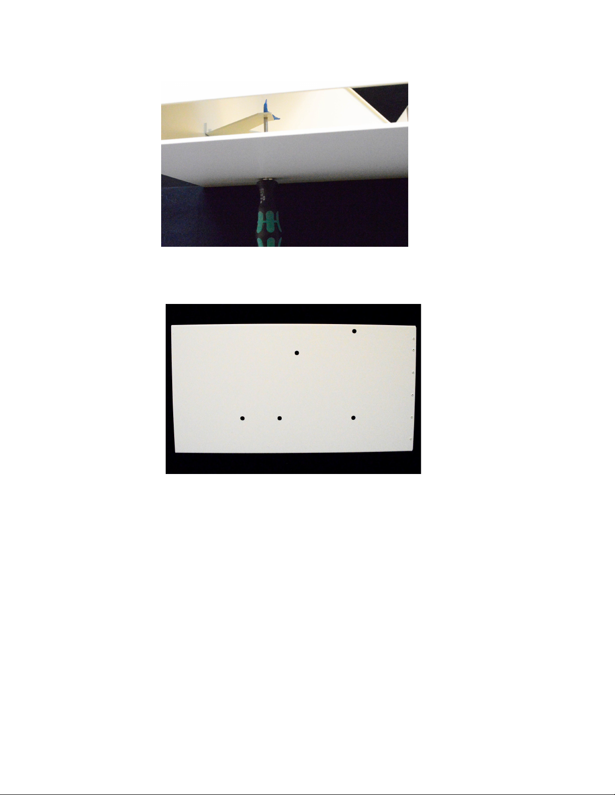
Cleaning- The spindle on the should be cleaned regularly. Cleaning the spindle with any sort
of liquid, except alcohol, is not recommended. A Q-tip with most of its fluff removed and a little
alcohol can be used to clean the inside of the spindle and collet. When cleaning the outside of
the spindle and the spindle housing it is best to have the air on
and then use a vacuum and dry
rag to remove any chips and dust that has accumulated.
3

Getting Started
When you first get your machine you will need to remove shipping bolts, install into the
enclosure, hook up an air supply, and install the tool.
Removing Shipping Bolts
Note, this step can be seen in video form here:
https://www.youtube.com/watch?v=2H1Mnk9O__w from 0:10 to 0:35
There are four shipping bolts installed in the Pocket NC in order to lock the axes in position and
prevent damage to the machine during shipment.
These bolts must be removed before the machine may be used. The bolts are M6x8x25
shoulder bolts. The 4 mm hex key is needed to remove them is included in the kit shipped with
the machine. The bolts are installed only hand-tight.
Do not discard the bolts. They should be retained with the rest of the machine packaging in
case the user needs to ship the machine in the future.
The locations of the 4 shipping bolts are shown in the images below. Two of the shipping bolts
are located behind the Y-axis. When the user is looking at the back of the machine they are
located in the lower-right quadrant of the machine.
4

The other two shipping bolts are located on the X-carriage behind the spindle. They are both
accessed from the top of the X-carriage.
5

Enclosure Installation
This section explains how to mount the machine into the enclosure. This can be a bit tedious,
but you only need to do it once as the machine will stay mounted inside the enclosure.
Materials Needed:
- (5) M4x6 screws*
- (5) rubber bumpers (optional)*
- Pocket NC V2 Enclosure
- Pocket NC V2 Mill
*Included in enclosure hardware kit
Tools Needed
- 3 mm hex driver or hex key
1) Remove the 5 feet from the machine (where the red arrows point to in the photo above
left).
2) Place the machine on the shelf inside the enclosure.
6

3) With the enclosure carefully overhanging a table or workbench as shown, start one of
the M4x6 fasteners into the screw hole closest to the USB port using a 3mm hex key.
4) Rotate the machine so the chip tray opening is hanging off the table and install one of
the M4x6 screws into the back of the machine.
7

5) Rotate the enclosure back to the first position and tighten the first screw.
6) Carefully place the enclosure on its back and fully open the lid to prevent it from opening
on its own.
7) Install the 3 remaining screws.
8) Clean off the bottom of the enclosure and stick on the 5 rubber bumpers if desired.
Note: This enclosure is not designed or intended for shipping with the PocketNC installed, make
sure to remove your machine before shipping!
If moving the enclosure be aware that the lid can pop open, secure it shut with tape if moving.
8

Connecting the Air Supply
Note, a video of connecting the air supply can be viewed here:
https://www.youtube.com/watch?v=2H1Mnk9O__w from 0:47 to 1:26
Below is an example of the air setup required to run the Pocket NC V2-50. Please note that the
source of air and inlet hose may differ. The user will need to supply and install the appropriate
adapter into the ¼” BSPT port on the inlet side of the filter in order to hook up the desired air
hose. Note the machine comes with the air regulator and filter (the tan colored piece of
equipment hanging on the pegboard in the photo below) as well as all black tubing. The
machine does not come with the red tubing or the air compressor shown on the left of the photo,
the user will need to supply input tubing and air supply.
9

In the setup above, the air supply is a Gast air compressor with ¼” air hose (red) supplying air to
the CKD filter and regulator that is included with the V2-50. The 4mm (black) hose supplies air
to the tee on the backside of the spindle, which supplies air to the internal air sensor. The tee
also carries the air to the spindle using a short length of 4mm hose connected to the blue
connection on the end of the spindle motor. It is important that air comes into the tee and then
out of the tee and into the spindle so that the machine recognizes that air has been provided.
The recommended air pressure for the V2-50 spindle is 25 psi or .17 MPa. This can be adjusted
using the knob on the bottom of the regulator by pulling down to unlock it and then turning to the
right for more pressure or the left for less. It is best to push the knob back up into its locked
position after adjustment to reduce the risk of accidental pressure adjustments.
For more information on the CKD air filter and regulator please visit:
https://www.ckd.co.jp/kiki/en/product/detail/38/M%E2%80%BB000
https://www.ckd.co.jp/kiki/en/product/detail/396/
10
Indice
Altri manuali Pocket NC Sistema di controllo


