PRO-TEK 3201 Manuale utente

99 Washington Street
Melrose, MA 02176
Fax 781-665-0780
TestEquipmentDepot.com

ⅰ
ⅰ

ⅱ
ⅱ
ⅲ
ⅲ

(1) Function mode: Displays the currently selected display (Spectrum, Bar graph, and Counter)
(see page 23)
(2) Scan mode: Displays the selected scan mode.3 types of scanning may be selected. See page
14 and 26 for manual scan, pages 17& 26 for search and pages 16 & 26 for channel scan.
(3) Title name: The data memory, which is, selected (page 37)
(4) Marker Frequency: The frequency in which the unit is currently tuned to as indicated by the
marker indicator.
(5) Ref.Level: The base line reference amplitude(0 level). The Reception modes (page 50)or the
selected external Attenuator value (page 46)sets this value.
(6) Marker Level: The amplitude value of the signal level the unit is currently tuned to as indicated
by the marker.
(7),(8) Center Frequency and Span are used in Manual scan and are described on page 14.
(9) Step Frequency: The scanning frequency increment value set by the .(page 49)
(10) Reception Mode: The type of modulation needed for aural reception of the incoming signal.
Note: a CW or a signal other than a Narrow Band FM(NBFM), wideband FM(WBFM), AM or SSB
may be displayed by selecting a reception mode which has the appropriate bandwidth
(see page 5).
The Reception mode is selected by pressing the button.
(11) Sweep Mode: Determines how the scan moves across the screen when the squelch is activated.
(See page 26)
(12) Displays the value of the squelch level (see page 51).
(13) Marker: Indicates the signal level currently being scanned
(14) Attenuator Value: Displays the amount of external attenuation connected to the input. When
an external Attenuator is used, the value of the Attenuator must be added to the Reference
level. This is accomplished through the ATT dB set in the system
F2
F3
Test Equipment Depot - 800.517.8431 - 99 Washington Street Melrose, MA 02176
FAX 781.665.0780 - TestEquipmentDepot.com

CONTENTS
Quick Main Menu set up guide …..……………………………………………………… ⅰ
Quick System Menu set up guide……………………………………………………..…. ⅱ
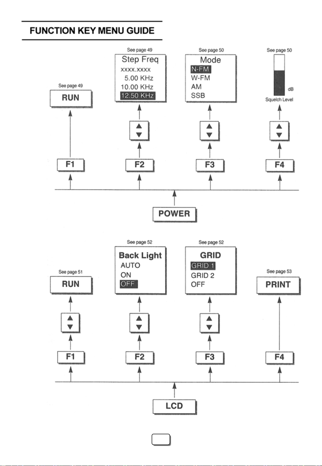
Function Key Menu guide ..………………………………………………………………. ⅲ
Display Description ………………………………………………………………………… ⅳ
Ⅰ. Introduction ……………………………………………………………..……………… . 4
1. General …………………………………………………………………..…………….. 4
2. Features …………………………………………………………………..…………….. 4
Ⅱ. Specifications ………………………………………………………………..………….. 4
Ⅲ. Precautions ……………………………………………………………………..………… 7
Ⅳ. Functional Description ……………………………………………………….………… 9
1. Panel Description …………………………………………………………….………… 9
Ⅴ. Basic operation ………………………………………………………………….…….. 12
1. General …………………………………………………………………………………. 12
1 Prior to connecting to a power source …………………………………………….. 12
2 Input connection …………………………………………………………………..…12
3 Powering the unit on ………………………………………………………………… 12
4 Entering a Frequency value …………………………………………………………. 13
5 Scanning ………….…………………………………………………………………. 13
6 Positioning the Frequency marker …………………………………………………. 14
7 Power Off …………………………………………………………………………….. 14
2. Manual Scan ………………………………………………………………………….. 14
3. Ch. Memory Scan ……………………………………………………………………… 16
1
1

4. Search Scan
5. Difference Mode
6. Frequency Counter
7. Recorder Mode
8. Power supply
1 Car and AC adapter
2 Battery Replacement
Ⅵ. Menu Description
1. The Main Menu
1 Main menu display
2 Function Modes
3 Scan Modes
4 Sweep Mode
5 Edit Channel
5-1 Selecting Edit Channel
5-2 Assigning a Channel number
5-3 Entering a Channel name
5-4 Insert Function
5-5 Delete Function
1-6 Setup Memory
6-1 Setup Memory
6-2 Save and Load setups
6-3 Title Names
1-7 Data Memory
7-1 Data Memory Setup
7-2 Saving and Loading
7-3 Title name
………………………………………………………………………… 17
…………………………………………………………………… 19
………………………………………………………………… 19
……………………………………………………………………… 21
………………………………………………………………………… 22
……………………………………………………………… 22
……………………………………………………………… 22
………………………………………………………………………… 23
……………………………………………………………………… 23
………………………………………………………………… 23
…………………………………………………………………… 23
………………………………………………………………………… 26
………………………………………………………………………… 27
………………………………………………………………………… 28
……………………………………………………… 28
……………………………………………… 30
…………………………………………………… 30
………………………………………………………………… 32
………………………………………………………………… 32
……………………………………………………………………… 32
…………………………………………………………………… 32
…………………………………………………………… 34
………………………………………………………………………… 35
………………………………………………………………………… 37
……………………………………………………………… 37
……………………………………………………………… 38
……………………………………………………………………… 38
2
2

8 SSB BFO
9 Hold Mode
10 Level Hold
2. The System Menu
1 System Menu display
2 db Unit
3 Power Off
4 I/O Menu
5 Printer Menu
6 Copy Set Mode
7 External Attenuators
8 Test Set Menu
9 SCRB Menu
10 Battery Check
11 Keyboard Buzzer
3. Function Keys…………
1 RUN
2 STEP
3 MODE
4 SQL (Squelch Level)
4. LCD Men
…………
u
1 LCD Contrast
2 LIGHT
3 GRID
4 PRINT…………
……………………………………………………………………………….. 39
……………………………………………………………………………… 39
…………………………………………………………………………….. 41
………………………………………………………………………… 42
………………………………………………………………… 42
………………………………………………………………………………….. 43
………………………………………………………………………………. 43
……………………………………………………………………………….. 44
……………………………………………………………………………. 44
………………………………………………………………………… 45
………………………………………………………………… 46
……………………………………………………………………… 47
………………………………………………………………………… 47
………………………………………………………………………. 48
………………………………………………………………………… 48
…………………………………………………………………….. 49
…………………………………………………………………………………. 49
…………………………………………………………………………………… 49
…………………………………………………………………………………. 50
…………………………………………………………………. 51
…………………………………………………………………………… 51
……………………………………………………………………… 51
…………………………………………………………………………………… 52
……………………………………………………………………………………… 52
…………………………………………………………………………… 53
3
3

I. INTRODUCTION
1. General
The 3201 is the world’s first hand-held RF Field Strength Analyzer.
With a wide band reception range of 100 KHz to 2060MHz, the 3201 is a compact and
Lightweight portable analyzer. It is the ideal tool for field RF technicians to test, install and
Maintain Mobile Telecommunications Systems, Cellular and Cordless Phones, CB Radios,
Paging Systems, Cable and Satellite TV systems as well as antenna site measurements and
Maintenance.
2. Features
•100KHz to 2060MHz measurement range
•Measures and demodulates Narrow Band FM(N-FM), Wide Banc FM(W-FM),
AM, Single Side Band (SSB) signals.
•Built-in 2GHz Frequency Counter.
•PLL tuning system for precise frequency tuning.
•Up to 160 channels may be scanned and displayed on the LCD
•Built-in Speaker
•192 X 192 pixel backlit LCD
•All functions are menu selectable
•Has a RS-232 and parallel interface
II. SPECIFICATIONS
Reception Frequency
Frequency range
Freq. Accuracy (TXO)
Freq. Accuracy (display)
Demodulation
Step frequency
Data memory
Set Up memory
Reception sensitivity
Scan spee
: 100KHz to 2060MHz
: ±3PPM
: ±25PPM
: N-FM, W-FM, AM, SSB
: 5KHz to 9995KHz in multiples of 5KHz and 6.25KHz
: Stores 10 displays of up to 160 Channels per display(1600)
: Stores 10 setups for each scan mode
: Approx.0 –6 dBµEMF.
(S/N: 12dB at N-FM, 10dB at W-FM)
: 12.5Ch./sec.max.
d
4
4

Input impedance
Max.Input voltage
Audio output
Level Measurement
N-FM mode Range
Resolution
Accuracy
Repeatability
Bandwidth
W-FM/AM/SSB Range
Resolution
Accuracy
Repeatability
Bandwidth
Spurious and Noise Level internally generated
: 50Ω (standard)
: Max. 5V RMS
: 120mW into 8Ω speaker
: -70 to –20dBmV(-10 to 40dBµV)for 300 to 1800MHz
-60 to –20dBmV(0 to 40dBµV)for 1 to 300MHz and 1800 to 2000MHz
: ±0.5dBµV
: ±3dB(at an ambient of temperature of 23℃±3℃)
: ±2dB
: Approx. 12.5KHz(-6dB)
: -60 to –10dBmV(0 to 50dBµV)for 300 to 1800MHz
-50 to –10dBmV(10 to 50dBµV)for 10 to 300MHz and 1800 to 2000MHz
: ±0.5dBµV
: ±3dB(at an ambient of temperature of 23℃±3℃)
: ±2dB
: WFM: Approx. 180KHz(-6dB), AM/SSB:Approx.2.4KHz(-6dB)
: -35dBc W-FM
: -45dBc for N-FM typical, below a full scale signal level frequency.
Functions
Display modes
Sweep modes
Scan modes
Hold modes
Level hold modes
Squelch function
Copy function
: Spectrum display
Multi Bar graph display(5, 10, 20, 40, 80, 160CH)
Single Bar graph display
Difference frequency display
Frequency measurement level display
: Single, Normal, Free Run, Free Single
: Manual, CH.Memory and Search scan
: Delay run, Delay hold and delay stop
: Max. Hold, Hold, 40mS, 100mS and 200ms peak hold
: Squelch level is displayed as a bar graph and a digital Readout. The
squelch level may be adjusted to any value from the reference level to
Full scale
: The copy set mode allows the contents of the Channel edit, Setup and
Data memories to be copied to an external device. Data may also be
written in to these memories from an external device.
Test Equipment Depot - 800.517.8431 - 99 Washington Street Melrose, MA 02176
FAX 781.665.0780 - TestEquipmentDepot.com
Indice
Altri manuali PRO-TEK Strumento di misura

PRO-TEK
PRO-TEK 9216A Manuale utente

PRO-TEK
PRO-TEK 3290N Manuale utente

PRO-TEK
PRO-TEK A734 Manuale utente

PRO-TEK
PRO-TEK B-810 Manuale utente

PRO-TEK
PRO-TEK 1006 Manuale utente

PRO-TEK
PRO-TEK A334M Manuale utente

PRO-TEK
PRO-TEK Z9216 Manuale utente

PRO-TEK
PRO-TEK B8000FD Series Manuale utente

PRO-TEK
PRO-TEK A434L Manuale utente

PRO-TEK
PRO-TEK WI Series Manuale utente


