Racelogic VIPS Manuale utente

Positioning VIPS User Guide
•01 - VIPS Introduction
•02 - VIPS Hardware Installation
•03 - VIPS Rover Connection to VBOX 3i
•04 - VIPS Site Configuration Software Overview
•05 - VIPS Using with a VBOX 3i/Standalone
•VIPS - Regulatory Information
•VIPS - CAN Output
•VIPS - PIN OUTS
•VIPS - Technical Specification
1

01 - VIPS Introduction
Overview
VBOX Indoor Positioning System uses a network of fixed beacons in set locations that communicate with a receiver
(rover) using Ultra Wideband (UWB) to measure position and speed where you cannot use GNSS signals. A minimum of
six beacons are required, and to ensure the optimum accuracy, a site survey must be carried out as part of the
installation, using either a handheld laser or a Total Station (if time is of the essence, a self-survey can also be
performed). Doing so means the exact location of each beacon is known which can then be shared with the rover
enabling it to calculate its location to centimetre level accuracy. The beacons are completely stand-alone and can be
battery powered, making the deployment very rapid.
Up to 250 beacons can be installed within a system, however a maximum of 12 beacons will be used at any one time by
the rover. To receive the best accuracies of position and angles, the maximum number of beacons available to a
solution (12) should be utilised within line of sight to the receiver.
The rover features an integrated VBOX IMU04 (Inertial Measurement Unit) for precise pitch, roll and yaw angular data. It
can also connect directly to an IMU04 enabled VBOX 3i, enabling additional parameters from the vehicle’s CAN bus to
be logged. Offering seamless integration between indoor and outdoor environments, the system can be used for high
dynamic applications and the rover will automatically connect to the nearest beacons in range.
The UWB receiver continuously communicates with the beacons and triangulates its position indoors. This data is
combined with the measurements from a highly accurate inertial measurement system, providing a real-time 3D position
and attitude measurement at 100 Hz, to within 2 cm. VIPS can achieve re-acquisition and full accuracy in less than 0.2
of a second, which is considerably faster than GNSS!
The system is designed for high dynamic vehicle test and validation procedures which are normally performed outside
using GNSS. Examples include acceleration, braking, handling, crash testing, tyre testing and ADAS sensor validation.
The system can also be used to fill in gaps in GNSS coverage in areas such as heavy tree cover, tunnels and urban
canyons.
https://en.racelogic.support//VBOX_Indoor_Positioning_System_(VIPS)/VIPS_User_Guide/01_-_VIPS_Introduction
2
eatures
• When combined with a VBOX 3i, the system
offers seamless integration between indoor
environments (using VIPS) and outdoor
environments (using GNSS).
• Centimetre level accuracy in areas off limits to
GNSS based systems.
• Small, rugged and low powered.
• Only one rover is required, featuring an integrated
VBOX IMU with Kalman filter to reduce noise and
errors in the data.
• Connects directly to a VBOX 3i data logger using
only one cable for simple configuration.
• A minimum of 6 and maximum of 250 beacons can
be installed in each location allowing continuous
coverage of indoor spaces up to 3.5 km long.
• Simple one time configuration either by Bluetooth or
serial cable (RS232).
• 100 Hz update and low latency for high dynamic
applications.
• The rover automatically connects to the nearest
beacons for optimum accuracy.
• Each beacon is numbered for simple installation.
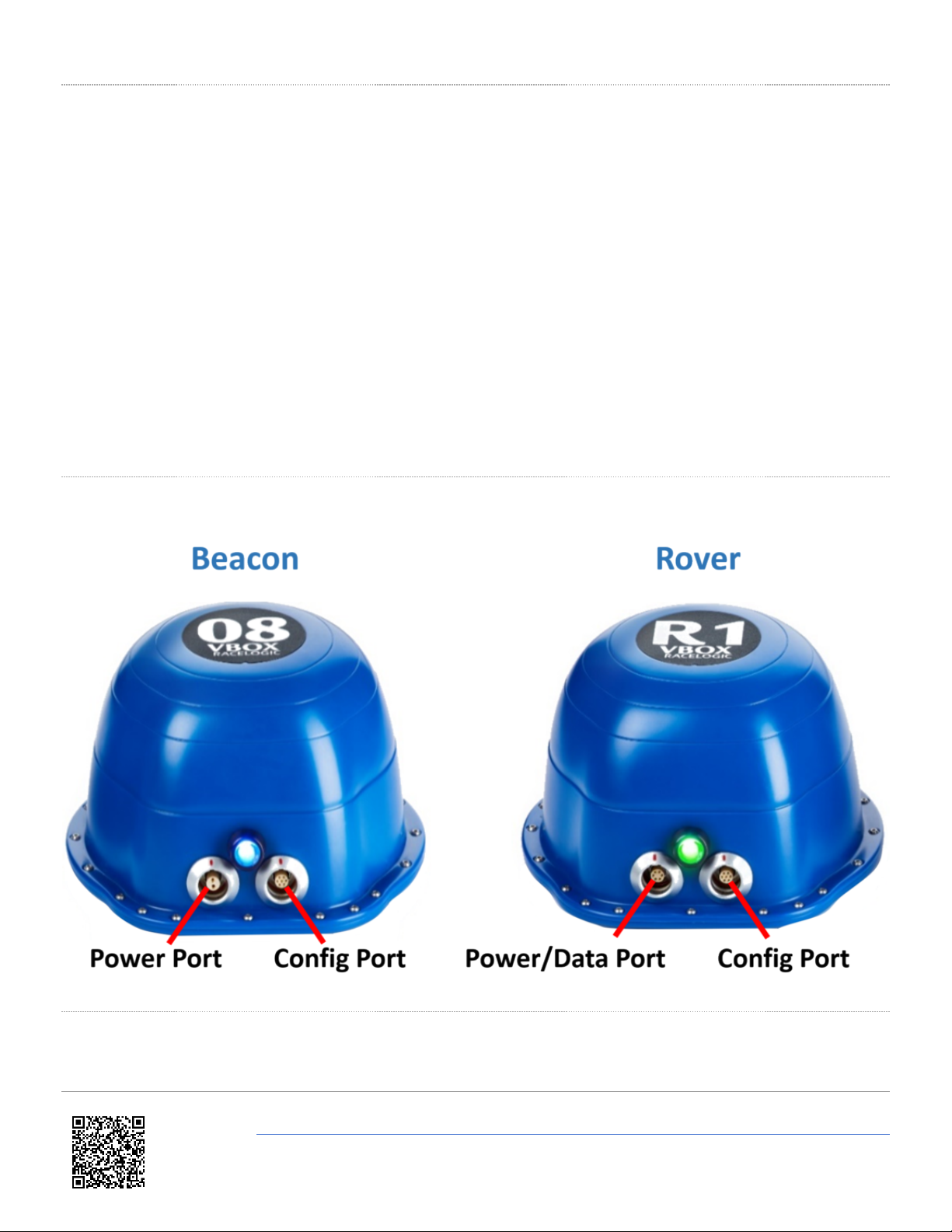
Connectors
LED Behaviour
The LED on the front of the Beacon and Rover units provides a visual status indication.
https://en.racelogic.support//VBOX_Indoor_Positioning_System_(VIPS)/VIPS_User_Guide/01_-_VIPS_Introduction
3

Beacon
LED Colour Status Description
Solid Blue The unit is Bootloader mode
Flashing Blue The unit is connected via an active Bluetooth link
Solid Green The unit has been used for ranging within the last
second
Blinking Green The unit is idle
Solid Red There is a non recoverable fault (such as an invalid reply
to a radio ID request)
Flashing Red The unit does not have a site configuration
Rover
LED Colour Status Description
Solid Blue The unit is Bootloader mode
Flashing Blue The unit is connected via an active Bluetooth link
Solid Green The rover is in 'Stand alone Mode' and receiving ranging
data from at least 3 beacons
Blinking Green The unit is looking for Beacons/ The unit is reading the
site information/ The unit is set to beacon mode
Flashing Green The rover cannot see at least 3 beacons
Flashing Orange The unit is syncing the IMU
Solid Orange The unit is waiting for VBOX communication (if VB3i
connected is selected)
Solid Red There is a non recoverable fault (such as an invalid reply
to a radio ID request)
https://en.racelogic.support//VBOX_Indoor_Positioning_System_(VIPS)/VIPS_User_Guide/01_-_VIPS_Introduction
4

02 - VIPS Hardware Installation
Beacon (VIPS-B-V1) Installation
When first considering a VIPS installation or demonstration, it is important to understand the shape and size of the test
area and thus the minimum number of beacons that will be required.
VIPS will need at least 6 beacons in view at any one time to compute a solution. or a simple installation, Racelogic
recommend placing the beacons in a ‘Square’ formation with spacing between the beacons of around 25–30 m, as
below.
The beacons require a 9 – 36 V power source that is connected to the 2 way Lemo connector. The other Lemo
connector on the beacon is for irmware upgrades and should be covered with the supplied splashproof plug to ensure
waterproofness.
https://en.racelogic.support//VBOX_Indoor_Positioning_System_(VIPS)/VIPS_User_Guide/02_-_VIPS_Hardware_Installation
5

The VIPS beacons have 4 magnets on the base allowing for easy installation onto any ferrous surface, however
Racelogic can supply metallic plates that can attach to a tripod for quick installations.
Beacon Installation Considerations
When mounting the VIPS beacons, there are considerations that should be made.
• If operating in an outdoor/indoor mode, then the rover will not switch to use the VIPS until 6 beacons are in view.
This means that it is only the first 6 beacons that will need to be placed closer together to ensure that 6 beacons are
in view before the vehicle enters the test area. The remaining beacons can be placed with a greater separation so
long as the vehicle is always within a 60 m radius of at least 6 beacons.
• or greater accuracy, it is recommended that the beacons are placed between 3–5 m above ground (i.e. above the
roof of the test vehicle) and that each beacon varies in height by at least 300 mm to the nearest beacons,
alternating in a high-low pattern.
• It is important when mounting the beacons that they are not mounted within at least 200 mm (or greater if possible)
of an object, other than the surface the beacon is mounted to, that could cause reflections (e.g. a wall or metal
structure) and that the beacons are mounted in the correct orientation in relation to the expected orientation of the
Rover when in use.
• The beacons can be mounted pointing up or pointing down, but remember to set the orientation in the Survey
Software.
• The majority of the beacons should be as high up as possible, however the area directly underneath the beacon (in
a small cone) gives poor reception if the prism and metal disc are retained.
• Some of the beacons (4 is a good number) should be at a lower level so that there is good variation in geometry.
Opposite to what you might think, It is much better to put the beacons as far away from the receiver as possible,
than getting them in close.
• The beacons should be turned so that the connectors on the beacon point towards the Robotic Total Station. This is
because the prisms are fitted so that they are aligned in the direction of the connectors, and it will give you the best
accuracy during the survey.
• Make sure you can clearly see all of the Prisms from the location of the Total Station. Try not to have two prisms in
line with each other from the view of the Total Station as it will be difficult to select the correct one.
• Bear in mind that the Total Station has a maximum upwards looking angle of 55°, so it won’t see a prism above this
elevation from the horizontal.
• Beacons can be mounted on metal and the feet are magnetic for this purpose, however the body of the beacon
should be kept at least 30 cm from any metal which is above the base. or example, the beacon in the image below
is in a bad location, to improve it, use something like a Smallrig extender arm to move it 30 cm from the metal. The
reason is that the metal will absorb and reflect some of the UWB signal, causing large inaccuracies and a reduced
range.
https://en.racelogic.support//VBOX_Indoor_Positioning_System_(VIPS)/VIPS_User_Guide/02_-_VIPS_Hardware_Installation
6

• To receive the best accuracies of position and angles, the maximum number of beacons available to a solution (12)
should be utilised within line of sight to the receiver.
Suitable Beacon Orientations
✔Side by side
https://en.racelogic.support//VBOX_Indoor_Positioning_System_(VIPS)/VIPS_User_Guide/02_-_VIPS_Hardware_Installation
7

✔Side by side with small height
difference
✔Side by side with large height
difference, tops towards each
other
✗✗ Side by side with large height
difference
✗✗ Tops together
✗✗ Tops to base
https://en.racelogic.support//VBOX_Indoor_Positioning_System_(VIPS)/VIPS_User_Guide/02_-_VIPS_Hardware_Installation
8

✗✗ Base to base
✗✗ Side to base
✗✗ Side by side with large height
difference, tops away from each
other
Rover (VIPS-R-V2) Installation
• The VIPS Rover looks similar to the Beacon, however the rover contains an internal IMU and so care should be
taken to ensure that the Rover is mounted to an area that has the least vibration. If being installed on a vehicle, this
is usually towards the rear, just in front of the rear windshield.
• The rover should be mounted in a way such that it has a clear view to the beacons and away from any objects that
may block that view (roof bars, radio antennas, etc).
• Make sure there is no metal close to the receiver, even a metal clamp close to the bottom of the receiver, or a
monitor in the line of sight to beacons can cause significant issues.
https://en.racelogic.support//VBOX_Indoor_Positioning_System_(VIPS)/VIPS_User_Guide/02_-_VIPS_Hardware_Installation
9

03 - VIPS Rover Connection to VBOX 3i
The Rover unit can connect to a standard VBOX 3i and switches seamlessly between GNSS and the indoor positioning
system, allowing you to use your original hardware for both outdoor and indoor testing. As the VIPS is designed to be
used with IMU Integration enabled, the same IMU Initialisation Process should be performed as normal.
or indoor only use, it is important that the VBOX 3i does not have a GNSS antenna connected. If the VBOX receives a
satellite signal, even a poor one, the timing will change from the internal clock to GNSS time, causing the VIPS system
to fail. the VBOX 3i will function the same as when using GNSS in terms of CAN In / Out, data logging (analogue, etc.)
and VBOX Test Suite use.
When indoor/outdoor operation is selected, the VIPS system will wait for GNSS lock and IMU synchronisation before
attempting to initialise the VIPS positioning.
https://en.racelogic.support//VBOX_Indoor_Positioning_System_(VIPS)/VIPS_User_Guide/03_-
_VIPS_Rover_Connection_to_VBOX_3i
10
Indice
Altri manuali Racelogic Strumento di misura

Racelogic
Racelogic RLVBTOUCH-M Manuale utente

Racelogic
Racelogic VBOX 20SL Manuale utente

Racelogic
Racelogic RLPBT-V1 Manuale utente

Racelogic
Racelogic RLACS277RLACS29 Manuale utente

Racelogic
Racelogic VBOX Touch Motorsport V1 Manuale utente

Racelogic
Racelogic Performance Box Touch V2 Manuale utente

Racelogic
Racelogic PBT-V1 Manuale utente

Racelogic
Racelogic RLACS184 Manuale utente


