REED ST-335 Manuale utente

reedinstruments
www com
Model ST-335
400A
AC Clamp Meter
Instruction
Manual

reedinstruments
www com
2
Table of Contents
Safety .........................................................................................3-4
Features......................................................................................... 5
Specications.............................................................................5-7
Instrument Description...............................................................7-8
Operating Instructions..............................................................9-11
AC Current Measurements.......................................................... 9
DC/AC Voltage Measurements.................................................... 9
µA DC/AC Current Measurements ............................................ 10
Resistance & Continuity Measurements .................................... 10
Diode Measurements................................................................ 10
Capacitence Measurements ..................................................... 11
Frequency or % duty cycle measurements ................................ 11
Temperature Measurements...................................................... 11
Data Hold ................................................................................. 12
Backlight................................................................................... 12
Zero Button............................................................................... 12
Manual Ranging........................................................................ 12
Battery Replacement................................................................... 12
reedinstruments
www com
3
Safety
International Safety Symbols
This symbol, adjacent to another symbol or terminal, indicates
the user must refer to the manual for further information.
This symbol, adjacent to a terminal, indicates that, under normal
use, hazardous voltages may be present
Double insulation
Safety Notes
• Do not exceed the maximum allowable input range of any function.
• Do not apply voltage to meter when resistance function is selected.
• Set the function switch OFF when the meter is not in use.
Warnings
• Set function switch to the appropriate position before measuring.
• When measuring volts do not switch to current/resistance modes.
• Do not measure current on a circuit whose voltage exceeds 240V.
• When changing ranges using the selector switch, always disconnect
the test leads from the circuit under test.
• Do not exceed the maximum rated input limits.
Cautions
Improper use of this meter can cause damage, shock, injury or death.
Read and understand this user manual before operating the meter.
• Always remove the test leads before replacing the battery. Inspect the
condition of the test leads and the meter itself for any damage before
operating the meter.
continued ...

reedinstruments
www com
4
Cautions con’t
• Repair or replace any damage before use.
• Use great care when taking measurements when the voltages are
greater than 25VAC rms or 35VDC. These voltages are considered
a shock hazard.
• Remove the battery if the meter is to be stored for long periods.
• Always discharge capacitors and remove power from the device under
test before performing Diode, Resistance or Continuity tests.
• Voltage checks on electrical outlets can be difcult and misleading
because of the uncertainty of connection to the recessed electrical
contacts. Other means should be used to ensure that the terminals
are not “live”.
• If the equipment is used in a manner not specied by the manufacturer,
the protection provided by the equipment may be impaired.
Input Limits
Function Maximum Input
A AC 400A
μA DC, μA AC 200mA 250V fast
acting fuse
V DC, V AC, Frequency, Duty Cycle 600V DC/AC
Resistance, Diode, Continuity,
Capacitance Test 250V DC/AC
Temperature (°C/°F) 60V DC/24V AC

reedinstruments
www com
5
Features
• High resolution, 0.1μA
• Temperature range to 1832°F/1000°C
• LCD display with backlight
• Data Hold and zero function
• Auto shut off and low battery indication
• Resistance to 20MΩ
• Diode test to 0.3mA
Specifications
Function Range & Resolution Accuracy (% of reading)
DC Current 400.0μA ± (1.5% + 3 digits)
4000μA
AC Current
400.0μA ± (2.0% + 5 digits)
4000μA
4.000 AAC ± (2.5% + 10 digits)
40.00 AAC
400.00 AAC ± (2.0% + 5 digits)
DC Voltage
400.0 mVDC ± (0.8% + 3 digits)
4.000 VDC
± (1.5% + 3 digits)40.00 VDC
400.0 VDC
600 VDC ± (2.0% + 3 digits)
AC Voltage
400.0 mVAC ± (0.8% + 10 digits)
4.000 VAC
± (2.0% + 5 digits)
40.00 VAC
400.0 VAC
600 VAC
Resistance
400.0 Ω ± (1.0% + 4 digits)
4.000KΩ
± (1.5% + 2 digits)40.00KΩ
400.0KΩ
4.000MΩ ± (2.5% + 3 digits)
40.00MΩ ± (3.5% + 5 digits)
continued ...

reedinstruments
www com
6
Function Range & Resolution Accuracy (% of reading)
Capacitance
40.00nF ±(5.0% reading + 10 digits)
400.0nF ±(3.0% reading + 5 digits)
4.000μF ±(3.5% reading + 5 digits)
40.00μF
100.0μF ±(5.0% reading + 5 digits)
Frequency
5.000Hz ±(1.5% reading + 5 digits)
50.00Hz ±(1.2% reading + 2 digits)
Sensitivity: 5~5kHz:10Vrms min.
5kHz~150kHz:40Vrms min.
@ 20% to 80% duty cycle
500.0Hz
5.000kHz
50.00kHz
150.0kHz
Duty Cycle
0.5 to 99.0% ±(1.2% reading + 2 digits)
Pulse width: 100μs - 100ms, Frequency: 5Hz to 150kHz
Sensitivity: 5~5kHz:10Vrms min.5kHz~150kHz:40Vrms min.
@ 20% to 80% duty cycle
Temp (type-K)
(probe accuracy
not included)
-50.0 to 400.0°C -50.0 to -20.0°C ± 7°C
-20.0 to 400.0°C ±(3.0% reading + 5 °C)
400 to 1300°C 400 to 1000°C
1000 to1300°C ±(3.0% reading + 5°C)
-58.0 to 400.0°F -50.0 to 0°F ± 14°F
0 to 400.0°F ±(3.0% reading + 7°F)
400 to 2372°F 400 to 1832°F
1000 to1300°F ±(3.0% reading + 10°F)
Clamp Size Opening 0.9” (23mm) approx
Diode Test Test current of 0.3mA typical;
Open circuit voltage 1.5V DC typical
Continuity Check Threshold <100Ω; Test current < 1mA
Low Battery Indication “ ” is displayed
Overrange Indication “OL” is displayed
Measurements Rate 2 per second, nominal
Input Impedance 7.8MΩ (VDC and VAC)
Display 4000 counts LCD
AC Current 50/60Hz (AAC)
AC Voltage Bandwidth 50/400Hz (VAC)
Operating Temperature 14 to 122°F (-10 to 50°C)
Storage Temperature -14 to 140°F (-30 to 60°C)
continued ...

reedinstruments
www com
7
Relative Humidity 90% (0°C to 30°C); 75% (30°C to 40°C);
45% (40°C to 50°C)
Altitude Operating: 3000m; Storage 10,000m
Over Voltage Category III 600V
Battery Two 1.5V “AAA” Batteries
Auto OFF approx. 30 minutes
Dimensions/Weight 200 x 50 x 35mm/200g
Safety
For indoor use and in accordance with Overvoltage
Category II, Pollution Degree 2. Category II includes
local level, appliance, portable equipment, etc., with
transient overvoltages less than Overvoltage Cat. III
Instrument Description
1 — Current Clamp
2 — Clamp Trigger
3 — Rotary Function Switch
4 — LCD Display
5 — ZERO Button
6 — Data Hold and Backlight Button
7 — Mode Select Button
8 — Range Delect Button
9 — Hz/% Duty Button
10 — COM Input Jack
11 — V Ω μA °C/°F Jack
12 — Battery Cover

reedinstruments
www com
8
Display Descriptions
1. DC Direct Currrent
AC Alternating Current
2. Minus Sign
3. 4000 Count (0 to 3999)
Measurement Reading
4. AUTO AutoRange Mode
5. ZERO ZERO Mode
6. Diode Test Mode
7. Audible Continuity
8. HOLD Data Hold Mode
9. °C/°F, m, V, A, K, M, Ω Units of Measure List

reedinstruments
www com
9
Operation
NOTICE: Read and understand all warning and precaution
statements listed in the safety section of this operation manual prior
to using this meter. Set the function select switch to the OFF position
when the meter is not in use.
AC Current Measurements
WARNING: Ensure that the test leads are disconnected from the meter
before making current clamp measurements.
1. Set the Function switch to the 400A, 40A or 4A range. If the range of
the measured is not known, select the higher range rst then move to
the lower range if necessary.
2.
Press the trigger to open jaw. Fully enclose one conductor to be measured.
3. The clamp meter LCD will display the reading.
DC/AC Voltage Measurements
1. Insert the black test lead into the negative COM terminal and the red
test lead into the positive V terminal.
2. Set the function switch to the V position.
3. Select AC or DC with the MODE button.
4. Connect the test leads in parallel to the circuit under test.
5. Read the voltage measurement on the LCD display.
reedinstruments
www com
10
µA DC/AC Current Measurements
1. Insert the black test lead into the negative COM terminal and the red
test lead into the positive µA terminal.
2. Set the function switch to the μA position.
3. Select AC or DC with the MODE button.
4. Remove power from the circuit under test, then open up the circuit at
the point where you wish to measure current.
5. Touch the black test probe tip to the negative side of the circuit.
6. Touch the red test probe tip to the positive side of the circuit.
7. Apply power to the circuit.
8. Read the current in the display.
Resistance and Continuity Measurements
1. Insert the black test lead into the negative COM terminal and the red
test lead into the positive terminal.
2. Set the function switch to the position.
3. Use the multifunction MODE button to select resistance.
4. Touch the test probe tips across the circuit or component under test.
It is best to disconnect one side of the device under test so the rest of
the circuit will not interfere with the resistance reading.
5. For Resistance tests, read the resistance on the LCD display.
6. For Continuity tests, if the resistance is < 100Ω, a tone will sound.
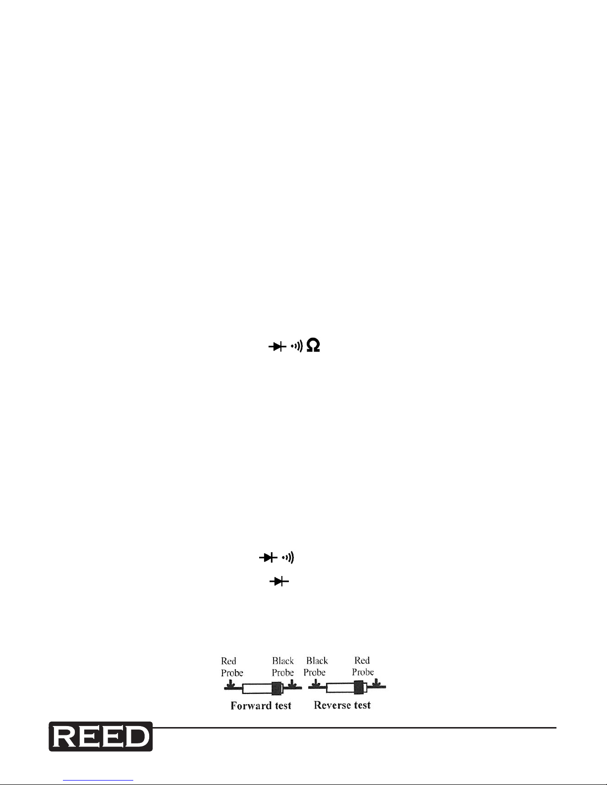
Diode Measurements
1. Insert the black test lead banana plug into the negative COM jack and
the red test lead banana plug into the positive diode jack.
2. Turn the rotary switch to the position.
3. Press the MODE button until “ ” appears in the display.
4. Touch the test probes to the diode under test. Forward voltage will
indicate 0.4V to 0.7V. Reverse voltage will indicate “OL”. Shorted
devices will indicate near 0mV and an open device will indicate “OL”
in both polarities.
Questo manuale è adatto per i seguenti modelli
1
Indice
Altri manuali REED Strumento di misura


