8• Description 65-2333 Hydrogen Cyanide Transmitter Operator’s Manual
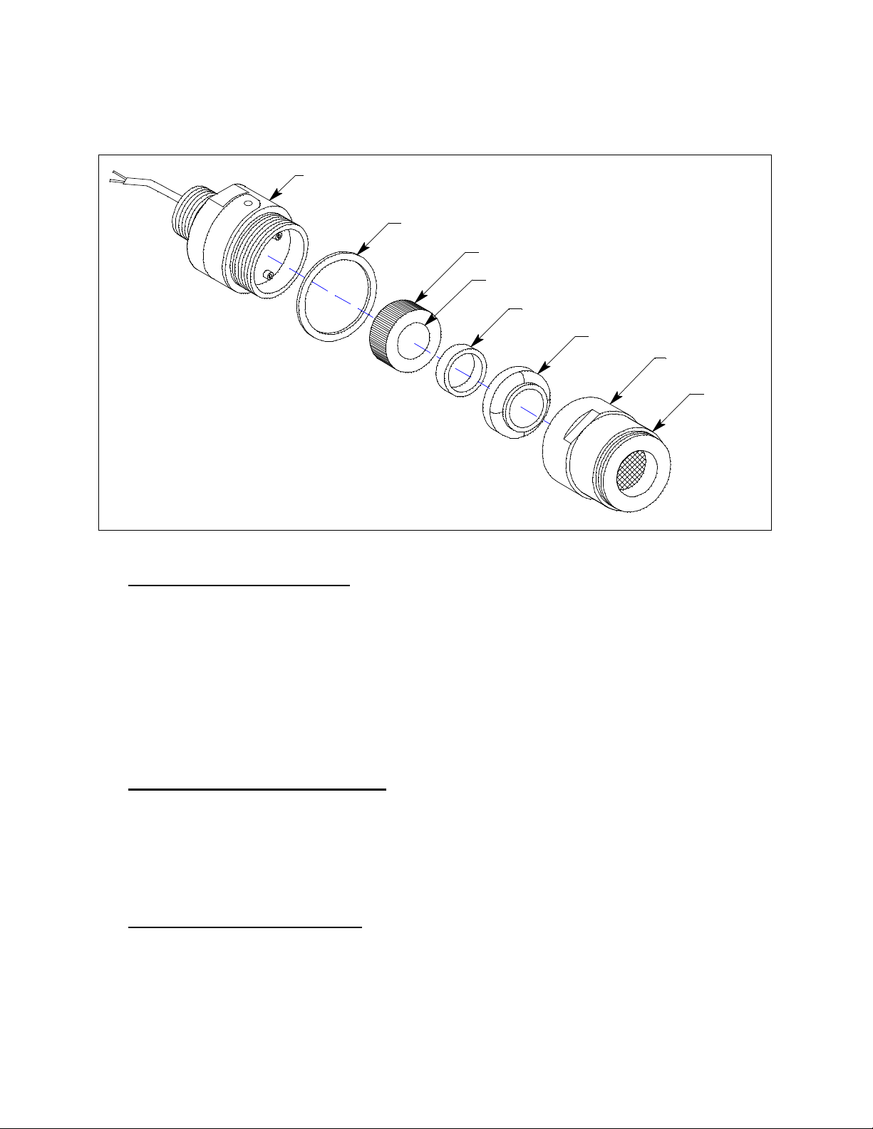
Plug-In HCN Sensor
The sensor is secured within the detector assembly by the housing cap. Through a series of
chemical and electrical reactions, the sensor produces an electrical output that corresponds to the
detection range of the transmitter. A VersaporR membrane is installed on the sensor face for
added protection from water and particulate contaminants.
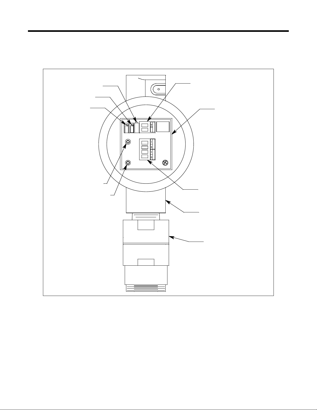
Amplifier
The amplifier converts the electrical output from the sensor to a 4 to 20 mA signal that
corresponds to the detection range and transmits the signal to a gas monitoring controller. A foam
gasket that orients the amplifier and keeps it from rotating is installed on the bottom of the
amplifier. The amplifier includes the controller terminal strip, detector terminal strip, zero pot,
span pot, and test points (Figure 1).
Controller Terminal Strip
The interconnect terminal strip is a two position plug-in style terminal strip located at the top edge
of the amplifier. Use the controller terminal strip to connect the amplifier to a controller.
Detector Terminal Strip
The detector terminal strip is a four-point plug-in style terminal strip near the bottom of the
amplifier. Use the detector terminal strip to connect the HCN detector to the amplifier.
NOTE: The HCN detector is factory-wired to the detector terminal strip. See “Installation” on
page 9 for all wiring procedures related to the transmitter.
Zero Pot
The zero pot is located in the upper left corner of the amplifier (see Figure 1). Use a small flat
blade screwdriver to turn the zero pot’s adjustment screw and adjust the amplifier’s zero (HCN
free) output during the start-up and calibration procedures. Turn the adjustment screw clockwise
to increase the zero output and counterclockwise to decrease the zero output.
Span Pot
The span pot is located to the right of the zero pot (see Figure 1). Use a small flat blade
screwdriver to turn the span pot’s adjustment screw and adjust the amplifier’s response output
during the calibration procedure. Turn the adjustment screw clockwise to increase the output and
counterclockwise to decrease the output.
CAUTION: The third potentiometer is factory-set. Do not adjust it.
Test Points
The test points (red and black) are on the left side of the amplifier (see Figure 1). The test points
produce a 100mV to 500 mV output that corresponds to the transmitter’s 4 to 20 mA output. Use
the test points and a voltmeter to measure the amplifier’s output during the start-up and calibration
procedures. The black test point in the lower left corner is the negative (-) test point and the red
test point below the zero pot is the positive (+) test point.