Setra Systems SRCM Manuale di installazione

1
Model SRCM
Operation

2
Contents
OPERATION......................................................................................................................................................................... 4
Condition Banner ................................................................................................................................................... 6
Condition Banner – Touch Screen ...................................................................................................................... 7
Operation................................................................................................................................................................. 7
Alarms Cause Condition Banner to Turn Red.................................................................................................... 7
Condition Banner Functions................................................................................................................................. 7
Operating Condition Screen ................................................................................................................................. 8
Pressure Value ......................................................................................................................................................... 9
Slider Bar and Set Point Values ............................................................................................................................. 9
Slider Bar On/O.................................................................................................................................................... 9
Active and Standby Modes .................................................................................................................................. 10
Menu Screens......................................................................................................................................................... 11
SETUP UNIT ...................................................................................................................................................................... 12
Room Parameters.................................................................................................................................................. 13
Analog Inputs ........................................................................................................................................................ 14
Changing Room Name......................................................................................................................................... 15
SETUP DISPLAY................................................................................................................................................................ 16
General Tab — Customizing the Condition Banner........................................................................................ 16
Advanced Tab–...................................................................................................................................................... 17
Customizing the Operation Condition Screen ................................................................................................. 17
Display Averaging (tenths of seconds)............................................................................................................... 17
What Pressure To Display.................................................................................................................................... 17
Pressure Resolution .............................................................................................................................................. 18
Supervisor and Operator Passwords .................................................................................................................. 18
Condition Banner Tab- Customizing Blinking Screens .................................................................................. 19
Full Screen Condition ......................................................................................................................................... 20
Banner and Active Standby Mode Application................................................................................................. 20
Set Time & Date Screen ....................................................................................................................................... 22
SETUP ALARM.................................................................................................................................................................. 22
Alarms Disabled when Door Open & Buzzer for Door ................................................................................. 24
Warning.................................................................................................................................................................. 24
Alarm Set Point ..................................................................................................................................................... 25
Alarm Matrix......................................................................................................................................................... 25
CALIBRATION AND SELF TEST..................................................................................................................................... 27
SYSTEM INFORMATION................................................................................................................................................. 28
USB CONFIGURATION CLONING................................................................................................................................. 29
UPDATING FIRMWARE................................................................................................................................................... 31
NETWORK SETUP............................................................................................................................................................ 32
EVENT LOG........................................................................................................................................................................ 34
FRENCH LANGUAGE SUPPORT ON DEFAULT SCREEN & DATA ENTRY SCREEN............................................. 35
Default screen for English version...................................................................................................................... 35
Default screen for French version....................................................................................................................... 35
Data Entry Screen for French Version ............................................................................................................... 36
TROUBLESHOOTING ...................................................................................................................................................... 41
RETURNING PRODUCTS FOR REPAIR ........................................................................................................................ 42
WARRANTY AND LIMITATION OF LIABILITY ........................................................................................................... 42

3
4
Operation
The following pages describe how to operate the SRCM using the touch-screen interface.
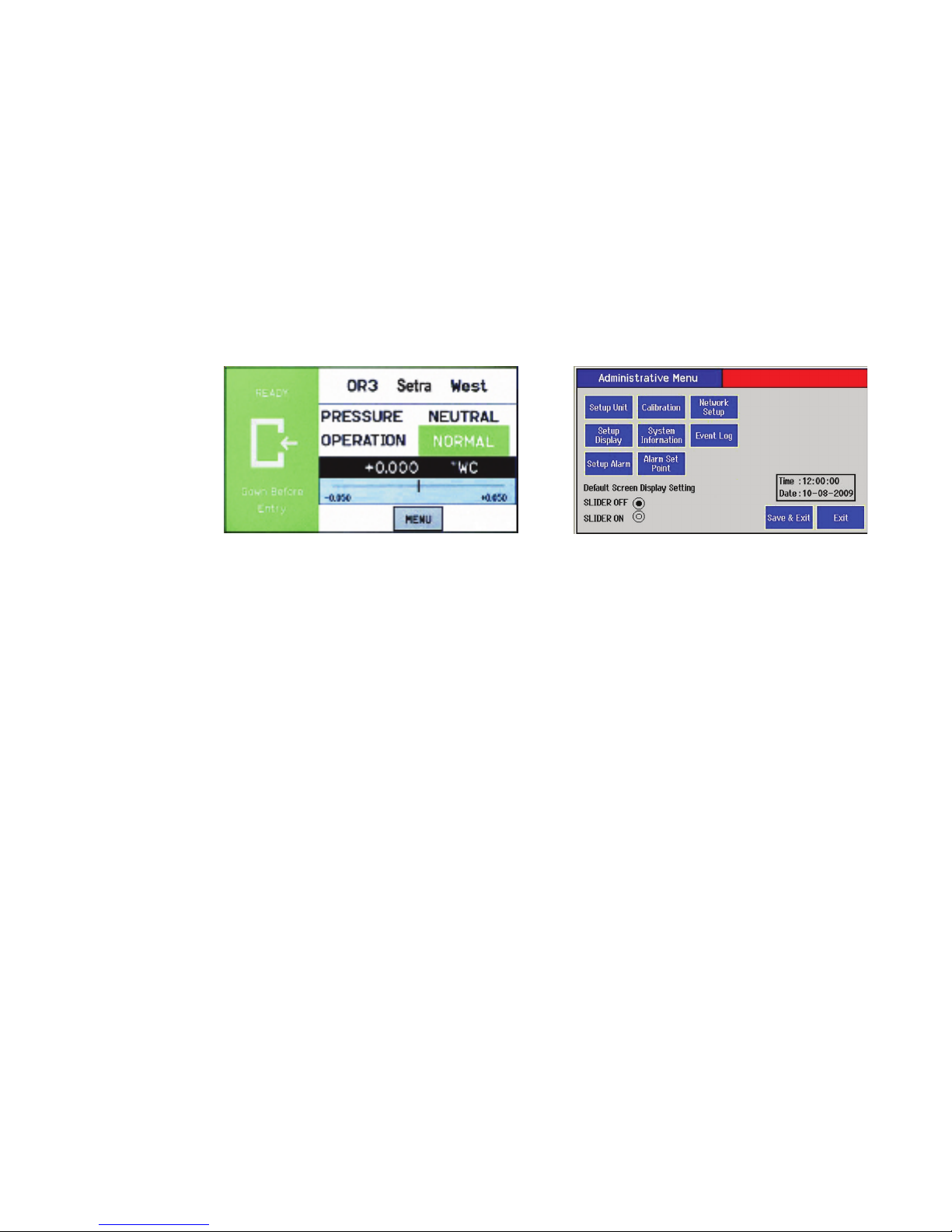
The screen has two basic functions. The primary mode of operation displays the Home
screen, which shows the end-user pressure values, messages, text, and other data intended
for visual pressure verication in the facility. The second mode of operation is the Ad-
ministrative Menu screen, which permits setup, conguration, and changes to how the
SRCM operates. After changes have been performed on the Menu screen, functions are
saved and operation returns to the Home screen. Note: If there is no user interaction with
the touch screen for more than 1 minute, the screen will automatically return to the Home
Screen. Many administrative settings can be written over the BACnet MS/TP network.
Home Screen Menu Screen
NOTE: All settings of the SRCM can be password protected.
5
The default screen now has 2 possible modes. If the user wants to display other room
variables in addition to Pressure they can switch to the alternate home screen that shows
up to 4 parameters per room. These Parameters can be Pressure, Temperature, Humidity,
and user-dened (ex: CO2). The User switches modes by selecting slider on/slider off on
the bottom of the administrative menu.
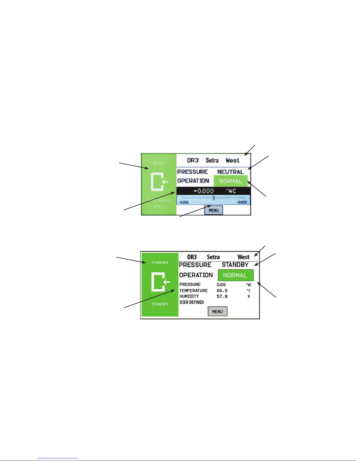
The Home screen is the normal continuous operating mode of the SRCM. The Home
screen shows a Condition Banner on the left one-third of the screen, and Operating Con-
ditions on the right two-thirds of the screen. There are two possible home screens, one
with a pressure only display with a slider bar representing the room pressure with respect
to the alarm setpoints. The alternate home screen can be used when there are multiple
parameters being measured in addition to pressure, such as temperature, humidity and a
user-dened option.
Pressure Value
Slider Bar and Setpoint Values
Condition Banner
Room Label
Pressure Mode
• Positive
• Negative
• Neutral (span)
• Standby
Operation
• Normal (green)
• Warning (yellow)
• Door (yellow)
• Alarm (red)
Alternate Home Screen displaying multiple
parameters, in addition to pressure.
Home Screen
Room Label
Pressure Mode
• Positive
• Negative
• Neutral (span)
• Standby
Operation
• Normal (green)
• Warning (yellow)
• Door (yellow)
• Alarm (red)
Pressure
Temperature
Humidity
User-dened
Condition Banner
Home Screen

6
The Condition Banner is the left 1/3rd portion of the screen that can be congured
by the end-user or facility manager to display a message to staff on the oor. The
Condition Banner can be Green, Yellow, Red or Blue, depending on the message
desired outside the pressurized space. The Condition Banner is set up in the Setup
Display-Condition Banner tab of the Administrative menu. There is also the op-
tion to display the Condition Banner in full screen.
The Condition Banner will change to red in alarm state regardless of the current
conguration. The banner may be changed manually, as required, by pressing the
touch-screen anywhere within the banner color region.
Green Condition Banner—shows the
Entry Permitted graphic, and user de-
ned text above and below the graphic
image. Use the GREEN banner to indi-
cate room is safe to enter.
Red Condition Banner—shows
the Stop graphic, and user dened
text above and below graphic im-
age. Use the RED banner to indicate
room is under critical use and entry
is restricted.
Yellow Condition Banner—shows the
Warning graphic, and user dened text
above and below graphic image. Use
the YELLOW banner to indicate room
is under transient use and entry is re-
stricted.
User dened text
ENTRY PERMITTED
graphic (arrow is not intended
to indicate direction of airow)
User dened text
User dened text
STOP graphic
User dened text
User dened text
Warning graphic
User dened text
Condition Banner
User dened text
ENTRY PERMITTED
graphic (arrow is not intended
to indicate direction of airow)
User dened text
BLUE Condition Banner—shows
the Entry Permitted graphic, and
user dened text above and below
graphic image. Use the BLUE ban-
ner to indicate room is safe to enter.
7
Once the messages of each of the four Condition Banners are dened in the Menu
section, the user can cycle through all four conditions by simply touching anywhere
on the left one-third of the screen. If passwords are enabled, the user will be prompted
to enter their password before proceeding. Each of the four colored screens can have
a unique message dened. See Section: Setup Display, page 11, for instructions on
how to setup the Condition Banner.
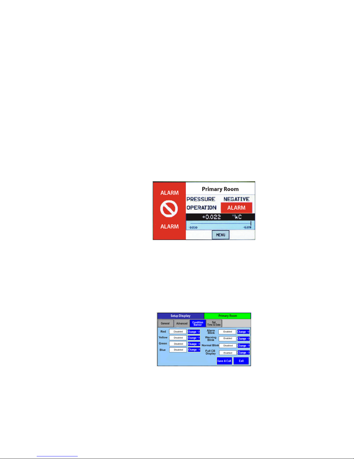
When the alarm occurs the Condition Banner will behave as follows:
1. Condition Banner will turn Red and Blink, irrespective of the color mode selected
by the user. User congured color mode: “Alarm Blink” & “Blink in Red” in the
Setup Display screen will remain same. The operation eld which displays the alarm
state of the system will also blink. When the system returns to normal user congured
settings will be retained.
2. The Message text on the bottom of the Condition Banner and User dened text on
top of the Condition Banner will be displayed as “ALARM” temporarily.
The Condition Banner can be congured so that any of the Condition Banner colors
can be set to blink when that condition occurs. For example if an alarm occurs, Red
color can be made to blink. Similarly, the yellow warning, green, and blue modes can
also be set to blink.
The Condition Banner conguration on the Display screen will have 3 options: Ac-
tive, Standby, and No Action for all four colors (Red, Yellow, Green, and Blue).
• When Active is selected, the Occupancy Status object of the SRCM will be active.
• When STANDBY is selected, then the unit shall be put into STANDBY mode (No
alarms will be generated) when the corresponding color condition is selected
• The No Action mode will do nothing other than to display the Condition Banner
screen that has been associated with the No Action mode.
Alarms Cause
Condition Banner to
Turn Red
Condition Banner
Functions
Condition Banner –
Touch Screen
Operation

8
Operating
Condition Screen
The Operating Condition screen shows the user the active operating conditions of the
pressurized space.
The Room Label at the top of the screen can be dened by the user to ensure the
viewer understands which room is being monitored by the SRCM. See Changing
Room Name page 10, to enter text for your specic room.
The PRESSURE indication shows the intended direction of airow for the space.
POSITIVE for airow out of the space, NEGATIVE for airow into the space,
NEUTRAL for airow conditions that may vary, and STANDBY for use when there
is no need to verify the direction of airow (alarms are disabled).
The OPERATION indication shows whether the pressurized space is within normal
operating parameters (within alarm thresholds), or whether there is an alarm or warn-
ing condition. If operation is within alarm thresholds, a green NORMAL indica-
tion is shown. If operation is near either high or low alarm threshold limits, a yellow
WARNING indication is shown.
If operation is at or beyond high or low threshold limits, a red ALARM indication is
shown. If Audible Alarming is Enabled, a piezo buzzer will sound and a SILENCE
menu button will appear. Pressing the SILENCE button will shut off the alarm for
the period of time dened in the alarm conguration. Alarm operation can be cong-
ured to blink or sound an audible signal. See Section, Alarm Setup, page 15, for more
about setting up ALARM and WARNING conditions.
In addition to the pressure indication, OPERATION also displays whether a door
is open. If a door switch is congured, an open door contact will display a yellow
DOOR indication.
Room Label
Pressure Mode
• Positive
• Negative
• Neutral (span)
• Standby
Operation
• Normal (green)
• Warning (yellow)
• Door (yellow)
• Alarm (red)
Pressure Value
Slider Bar and
Alarm Setpoint
Values

9
Pressure Value A black banner displays the actual pressure reading from the space, in either inches
of Water Column (“ WC) or Pascals (Pa). The resolution of display can vary, de-
pending on desired conguration; either 2, 3, or 4 signicant digits. The accuracy of
measurement remains the same regardless of the number of digits chosen.
The blue banner below the pressure value shows where the current pressure reading
is in relation to alarm setpoints. The value at the left of the blue banner is the low set-
point, and the value on the right is the high setpoint. The middle “I-beam” represents
the current measured pressure value on the setpoint scale.
If the user does not wish to see the actual slider bar, it can be turned off using the
Menu screen. Operation of the pressure sensing and alarming is unaffected. See set-
ting up Menu screen, page 7.
High alarm setpoint
“Cursor” representing where
the pressure value lies relative
to the alarm setpoint
Pressure Value
Slider Bar and
Setpoint Values
Slider bar is turned off, this dis-
plays when four parameters are
congured
Slider bar is turned off, this displays
when no parameters are congured -
Pressure still displays
Slider Bar and
Set Point Values
Slider Bar On/Off
10
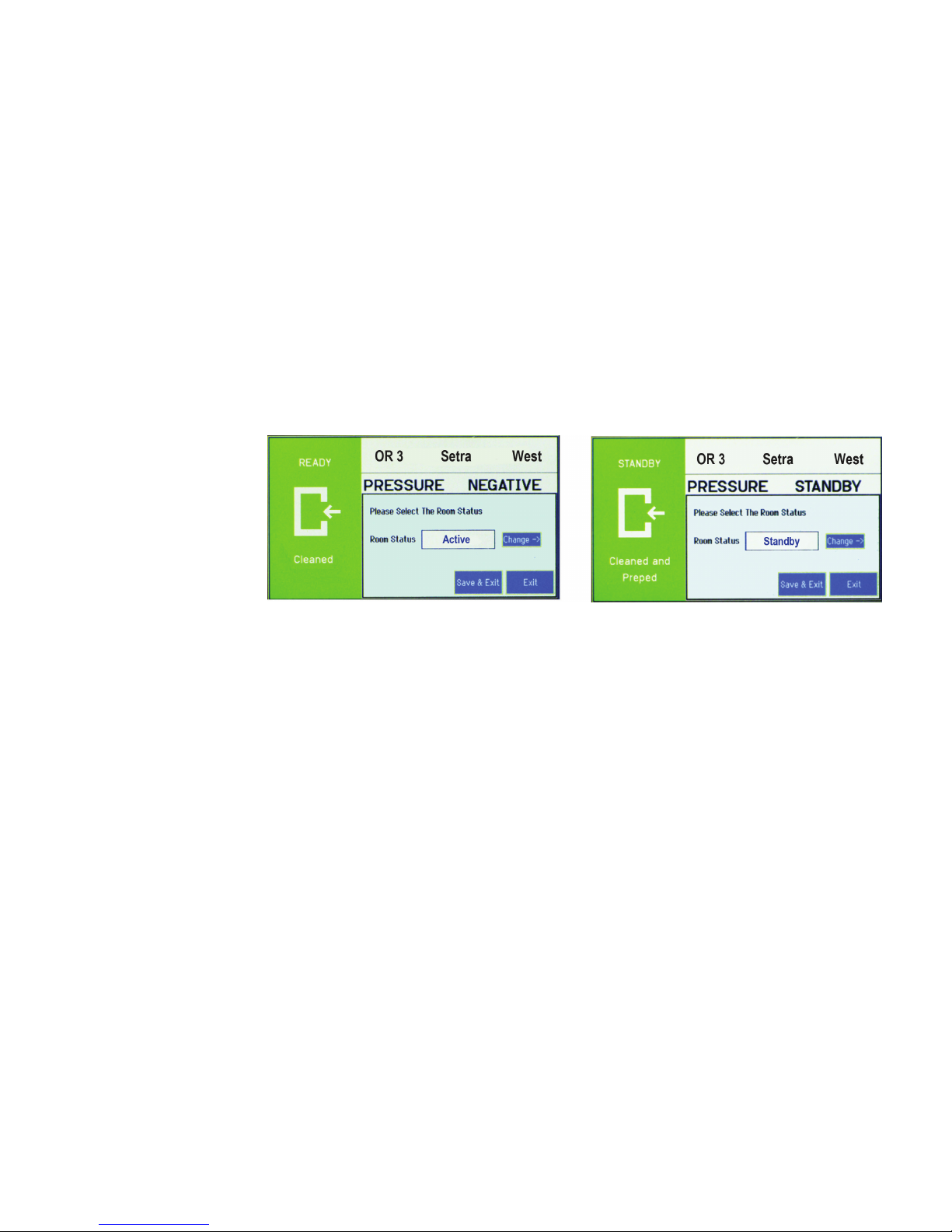
By pressing the touch-screen directly on the word POSITIVE (or NEGATIVE,
NEUTRAL, or STANDBY), the user is able to change the condition of the
room between ACTIVE and STANDBY modes. A pop-up menu appears to en-
able selection. If passwords are enabled, the user must rst enter a password to
proceed with the change.
In ACTIVE mode, the full function of the SRCM is active. In STANDBY
mode, the SRCM will perform all functions except that alarming will be dis-
abled (both audible and visual alarms). The STANDBY mode is designed to
put the SRCM into a mode where room pressurization is not critical, such as
cleaning, patient transfer, or longer-term unoccupied status. Note that this op-
eration can be password protected so that only an Operator or a Supervisor can
make this change. Passwords are set up in Setup Display Advanced tab.
Active and Standby
Modes
Altri manuali per SRCM
1
Indice
Altri manuali Setra Systems Strumento di misura

Setra Systems
Setra Systems SS-SPM Manuale utente

Setra Systems
Setra Systems SRIM1 Manuale utente

Setra Systems
Setra Systems Model 730 Manuale utente

Setra Systems
Setra Systems DATUM 2000 Manuale utente

Setra Systems
Setra Systems 760 Manuale utente

Setra Systems
Setra Systems Power Patrol Manuale

Setra Systems
Setra Systems 761 Manuale utente

Setra Systems
Setra Systems SRIMV Istruzioni operative

Setra Systems
Setra Systems 370 Manuale utente

Setra Systems
Setra Systems MRMS Manuale utente


