LCR-Reader-MP Manual Siborg Systems Inc. 6
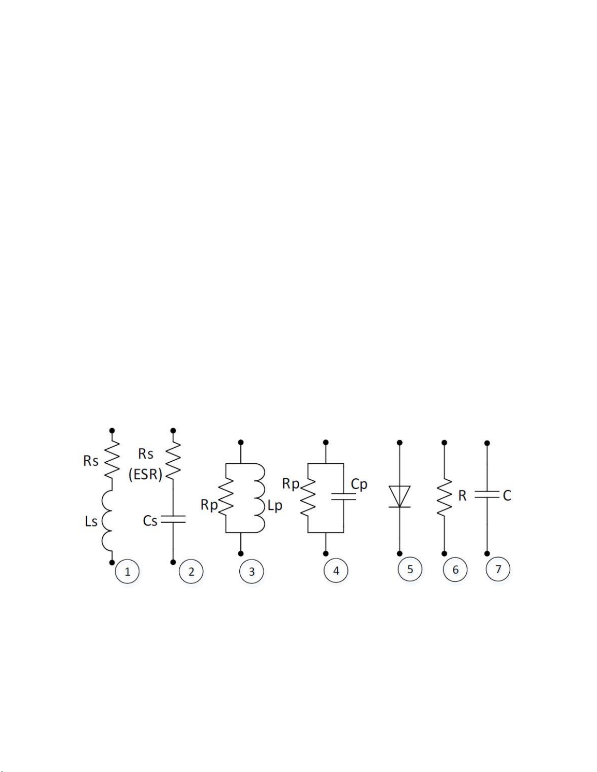
Inductance L = Xs/(2πf). Q = |Xs|/Rs. D = 1/Q. |Z| =
The device automatically selects the optimum frequency and the equivalent circuit for
measurements. Users can also manually select measurement mode and frequency of the test signal
can be selected from 100 Hz to 100 kHz. Test voltage can be set to 0.65 Vrms and 0.1 Vrms.
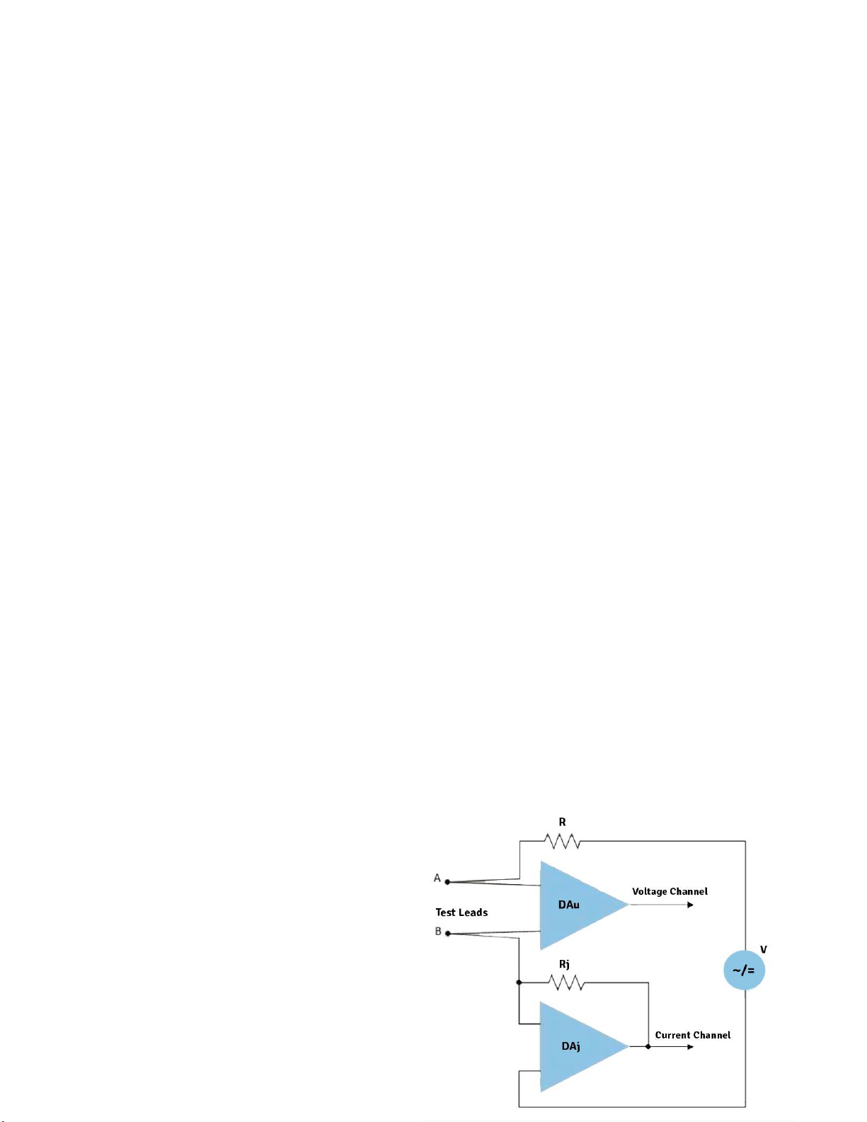
By passing direct current through the measured component, the voltage and current can be
measured. Using Ohm’s law, the DC current Resistance (R) can be calculated [6].
By applying the DC voltage in forward and reverse direction, the diodes [5] are detected and the
polarity of p-n junction is determined.
Charging and discharging the capacitor [7] by changing the voltage on the measured component for
a fixed time interval to determine capacitance for capacitors above 40 mF.
The principle of the frequency counter is based on the counting pulses of the reference generator
between the two ramps of the input signal for a certain period of time (by default about 1 second).
At the same time, the quantity of periods of the input signal is counted too. Then the frequency fis
calculated by the formula f = M/N* frwhere f is the number of periods of the input signal, M is the
number of periods of the input signal, N is the number of pulses from the reference generator and fr
is the frequency of the reference generator
The principle of measuring the voltage is based on comparing the input signal with the reference
voltage.
5 Safety Measures and General Instructions
For safe and reliable operation of the device, follow these rules:
1. Excersize additional caution when measure the capacitance, inductance, resistance and diodes
in a circuit with voltage applied
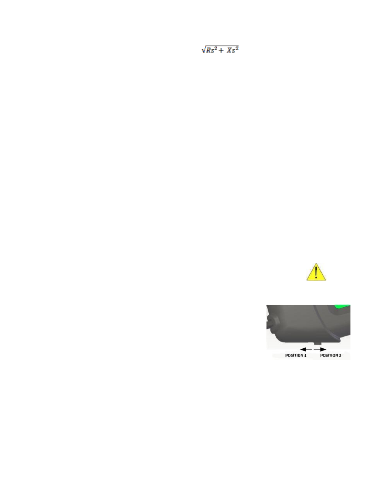
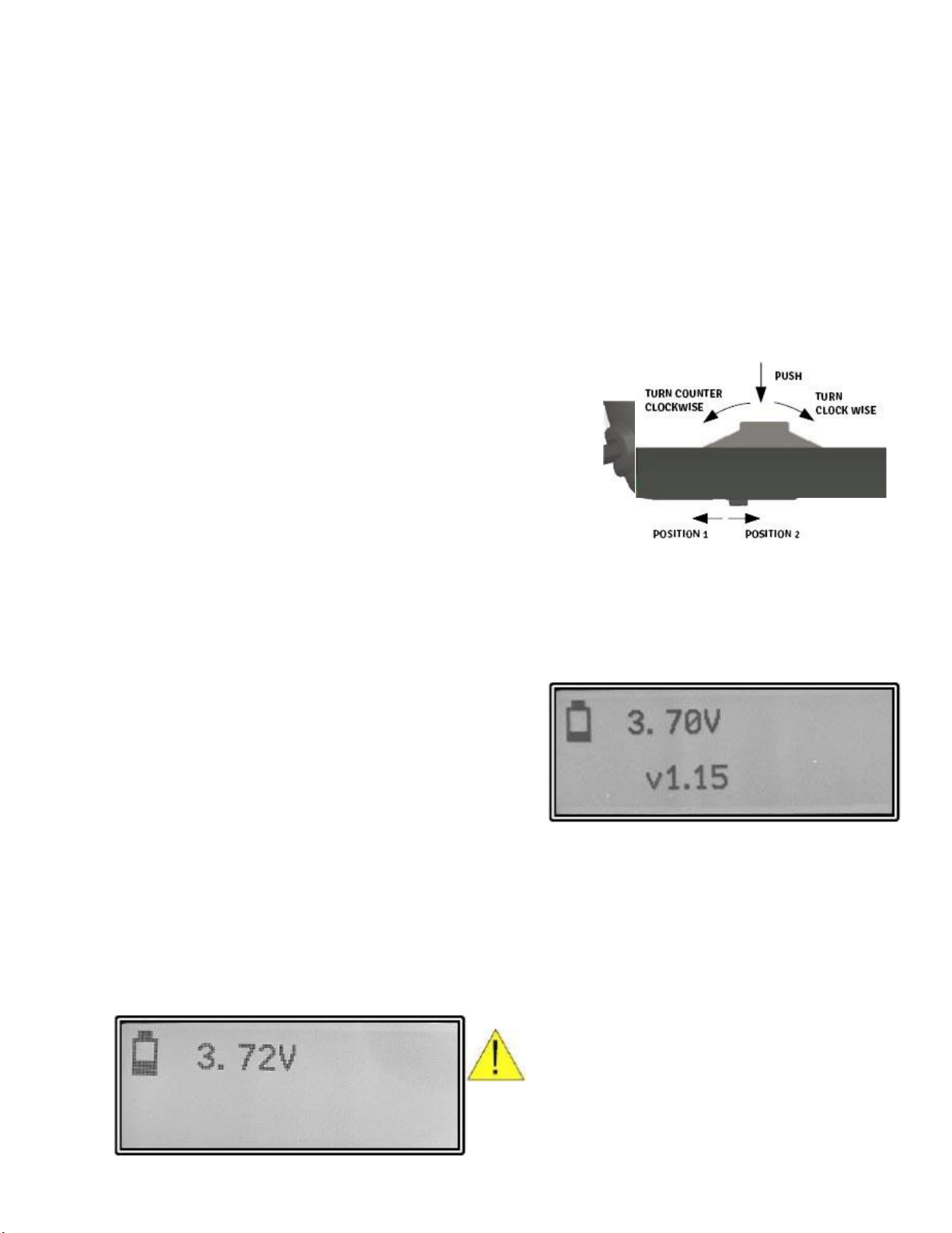
2. Never apply more than 20V DC or 14 Vrms to the probes with the
device switch in position 2.
3. Never apply more than 1.5 V DC or 1.0 Vrms to the probes with the
device switch in position 1.
4. Never measure Charged Capacitors
5. Do not make measurements while the device is charging
6. Charge the battery using a USB port of a computer or a DC charger 5 V +/- 5%. Do not use
damaged cables or chargers. Charging in the presence of moisture may cause fire, electrical
shock, injury or damage to the device or other property.
7. Do not stretch the handles for more than 20mm between the test leads.
8. This device is designed for indoor use.
9. To prevent injury from sharp ends of the test leads, transport the device in the case.
10. Do not touch non-insulated test lead surfaces during measurements. Keep fingers on the
insulated surfaces of the handles.
11. Replacement of the battery must be carried out by a specialist. Batteries must be recycled or
disposed of separately from regular household waste. Do not burn the battery.