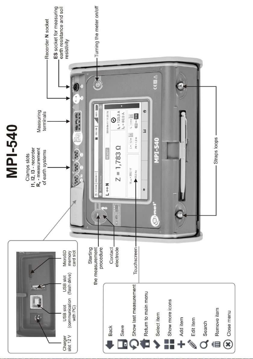
MPI-540 –BRIEF USER MANUAL
CONTENTS
1Security.............................................................................................................4
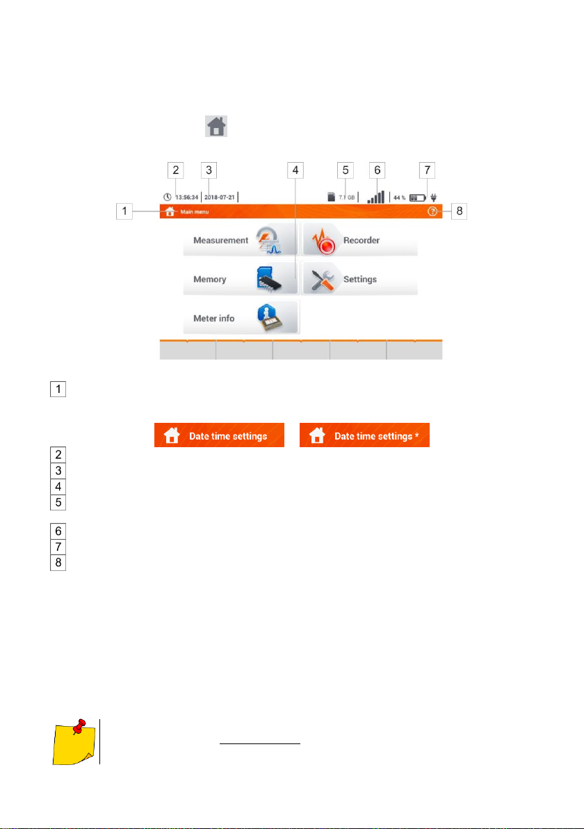
2Main menu ........................................................................................................5
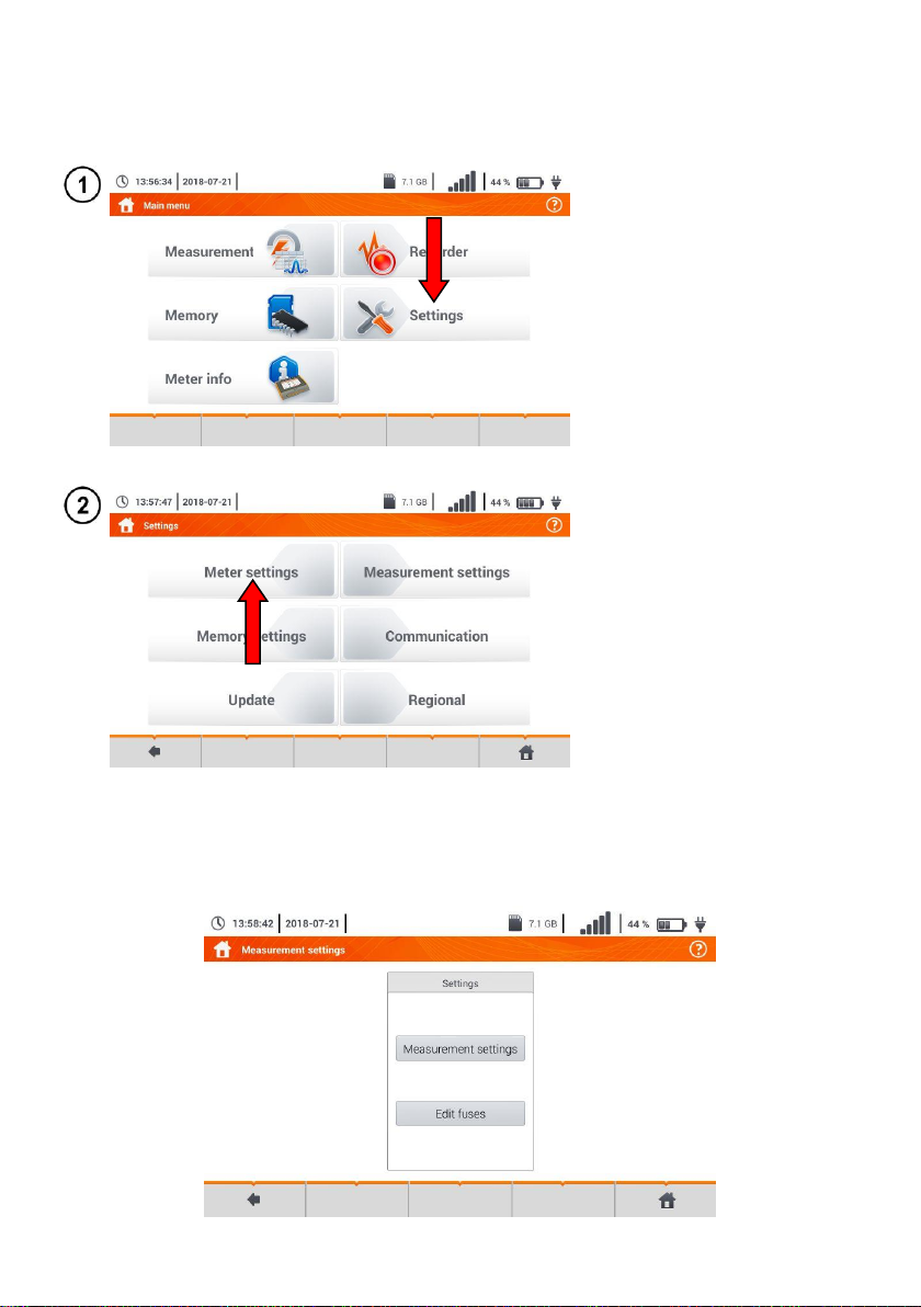
2.1 Meter settings...........................................................................................................6
2.2 Measurement settings..............................................................................................6
2.2.1 Sub-menu Measurement Settings....................................................................................7
2.3 USB communication.................................................................................................7
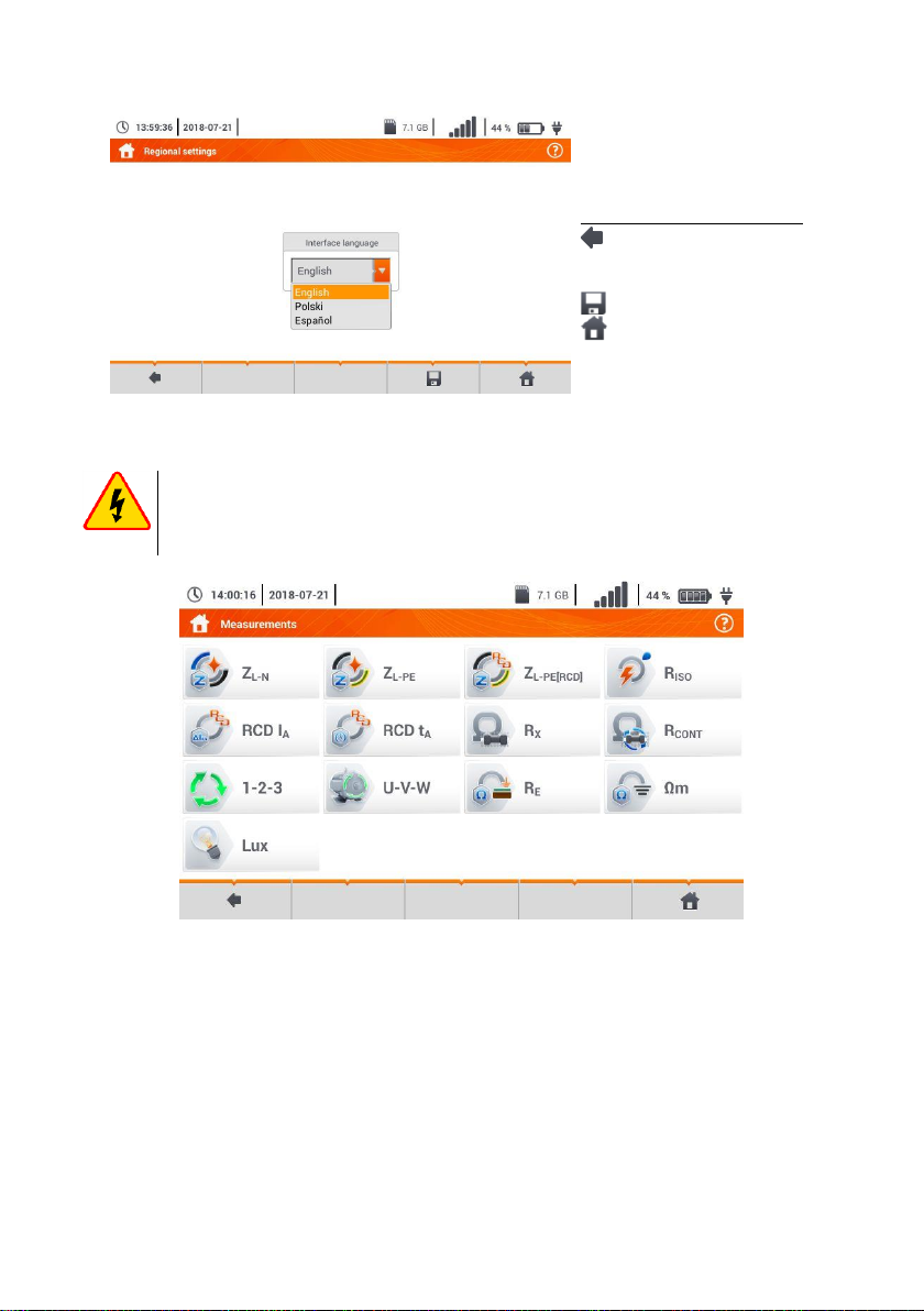
2.4 Regional settings ..................................................................................................... 8
3Measurements..................................................................................................8
3.1 Checking the correctness of PE (protective earth) connections ..............................9
3.2 Measurement of fault loop parameters .................................................................. 10
3.2.1 Measurement of fault loop parameters in the L-N and L-L circuits .................................10
3.2.2 Measurement of fault loop parameters in the L-PE circuit..............................................11
3.2.3 Measurement of fault loop impedance in L-PE circuit protected with a residual current
device (RCD).................................................................................................................12
3.2.4 Measurement of fault loop impedance in IT networks ....................................................13
3.3 Measurement of resistance to earth.......................................................................14
3.3.1 Settings of measurements .............................................................................................14
3.3.2 Measurement of resistance to earth using 3P method...................................................14
3.3.3 Measurement of resistance to earth using 4P method...................................................15
3.3.4 Measurement of resistance to earth using 3P + clamps method....................................16
3.3.5 Measurement of resistance to earth using double clamp method...................................17
3.4 Measuring soil resistivity........................................................................................18
3.4.1 Settings of measurements .............................................................................................18
3.4.2 Soil resistivity measurements ........................................................................................19
3.5 Measurement of RCD parameters .........................................................................20
3.5.1 Settings of measurements .............................................................................................20
3.5.2 Measurements in IT networks........................................................................................21
3.6 Measurement of insulation resistance.................................................................... 22
3.6.1 Settings of measurements .............................................................................................22
3.7 Low-voltage measurement of resistance ...............................................................24
3.7.1 Measurement of resistance............................................................................................24
3.7.2 Measurement of resistance of protective conductors and equipotential bonding with ±200
mA current.....................................................................................................................25
3.8 Checking sequence of phases............................................................................... 26
3.9 Checking the motor rotation direction ....................................................................27
3.10 Illuminance measurements .................................................................................... 28
4Recorder .........................................................................................................29
4.1 Functional description............................................................................................ 29
4.2 Main elements of the screen..................................................................................31
4.2.1 Main menu.....................................................................................................................31
4.2.2 Information bar on the parameters of the current network..............................................32
4.2.3 Help...............................................................................................................................32
4.3 Connecting the measuring system......................................................................... 32
4.3.1 Measuring arrangements...............................................................................................32
4.3.2 Recording configuration.................................................................................................35
4.4 Analyzer settings....................................................................................................36
4.5 LIVE mode of the network......................................................................................37
4.5.1 Transient waveforms of current and voltages (waveforms)............................................37
4.5.2 Timeplot of effective values ...........................................................................................37