spectrotec TORNADO 2000 Manuale utente

Contents
page
1 Application
1.1 Designates use 1
1.2 Non-designated use 1
1.3 Technical data 2
2. Safety instructions 2
3. Labelling 3
4. Start-up 3
5 Operation and maintenance 4
6 Shut-down 4
7 Gas saving mechanism 4
8 Repair 4
5. Operation and maintenance
5.1 Make shure that seals, sealing surfaces and pressure gauges are in good status.
5.2 Pressure regulators are always to be protect against damage (visual inspection in
regular intervals).
5.3 In case of malfunctions, e. g. an increase of the outlet pressure during the supply,
or in case of leakage versus atmosphere or a defective pressure gauge, shut down
the upstream gas supply and take the pressure regulator out of operation.
6. Shut-down
6. 1 For short-term interuption of work, it is sufficient to close the shut-off valve at
the consumer unit.
6. 2 For longer interuptions or to end the work, close shut-off valve (1) first. After the
pressure regulator has been depressurised, release the hand knob (4). Close shut-
off valve at the consumer unit.
6. 3 Before disassembling the pressure regulator, make sure that all pressure gauges
display zero.
!
!
7. Gas saving mechanism
Saving of inert gas with certain operation conditions
During frequent burner circuits a substantial gas saving can be obtained by connection
of a gas saving device at the outlet side.
The system has to be used according to these instructions for use and especially
the safety instructions!
1. Application
1.1 Designated use
Use the pressure regulator for tapping points TORNADO 2000 with an suitable
shut-off valve for gases dissolved under pressure, compressed or liqufied gases.
The pressure regulator TORNADO 2000 reduces an inlet pressure
1.2 Non-designated use
Do not use the pressure regulator for gases in the liquid phase.
to an as
constant as possible outlet pressure.
Do not use for unsuitable types of gas or corrosive gases.
Do not use at temperatures below -30°C or above +60°C.
!
!
!
8. Repair
8.1 Repairs may only be carried out by expert
persons.
8.2 Only original spare parts must be used. The materials have been adapted to the
gas type in each instance. So always specifiy the gas type.
8.3 In case of independent repairs, the use of non-original spare parts or changes on
the side of the user or a third party without the approval of the manufacturer, any
form of liability for resulting damages will expire as well as the manufacturers
warranty.
8.4 After being repaired, the pressure regulator must be checked with respect to
proper function, leak-tightness and cleanliness of the gas-wetted surfaces.When
the system is used again, a sufficient purging operation must be carried out first.
in authorized repair workshops
Instructions for use
TORNADO 2000
Pressure regulator for tapping points
Flow rate indication by pressure gauge
-4- -1-
GES_ET2000-MM Edition 0211
Subject to alteration without prior notice
© Spectron Gas Control Systems GmbH
tec
spectro
3. Labelling
4.3 Connect the pressure regulator to the closed gas cylinder valve (1). Tighten it gas-tight
with a suitable spanner.
4.4 Corresponddence between flow rate and orifice-diameter:
Inspection stamp confirming successfully passed test
1 Pressuere regulator for tapping
points TORNADO 2000
2 Gas type
3 Ordering-no.
4 Max. inlet pressure
5 Flow rate indication
6 Date of manufacture
ET 2000 - Ar
P1: 40 bar P2: 16 l/min
717. …
0500
1 2 3
456
!
1 3 4
25
6
1.3 Technical data
Indication range [l/min] Gas type Orifice diameter [mm]
up to 16
up to 30
up to 50
Argon, CO2
Mitrogen-hydrogen 80/20
0,55
0,75
0,85
Argon, Co2
The pressure regulator TORNADO 2000 conforms to the latest standard DIN/EN/ISO 2503
For special versions, this standard is taken into account as appropriate.
4. Start-up
4.1 Before starting read the specifications of this instruction for use and observe it while
working.
4.2 Check, that the cylinder valve thread, the pressure regulator connector and the
connection seals are without any damage (blow through if nessesary).
Do not use the pressure regulator if damaged.
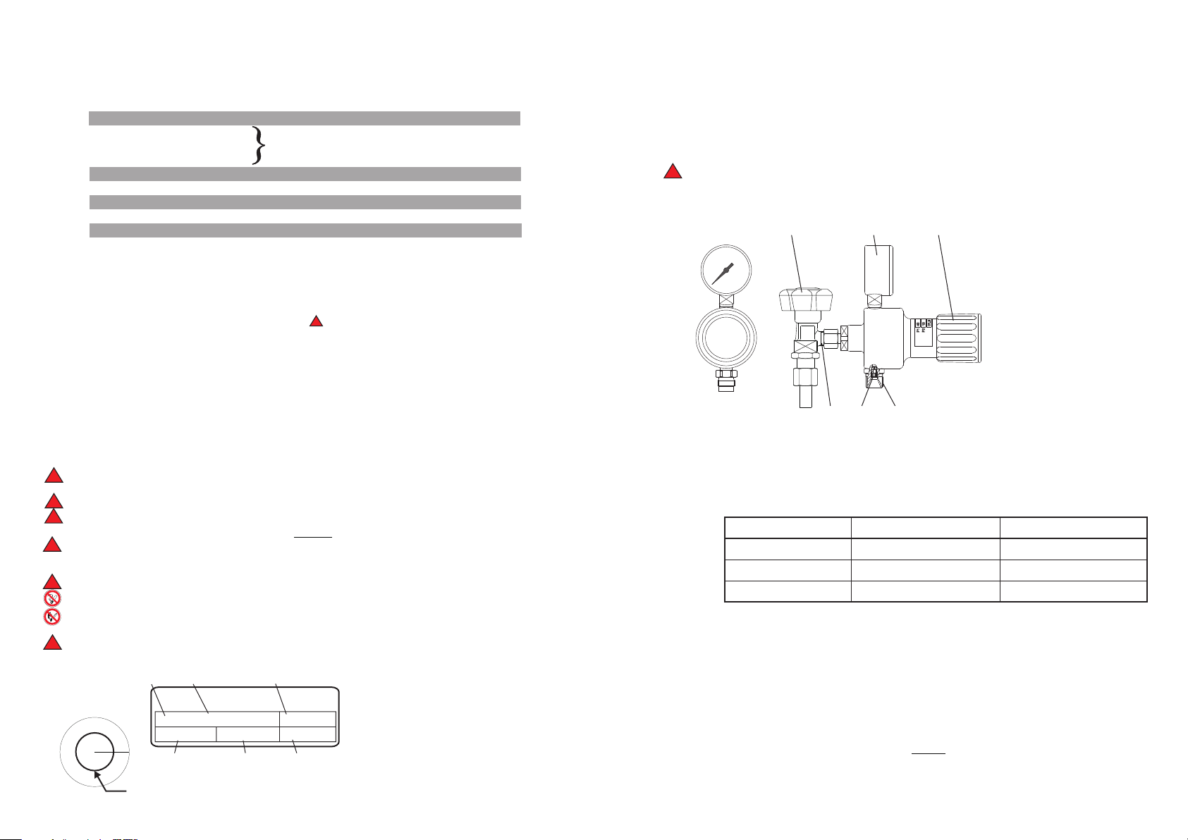
1 Shut-off valve
2 Shut-off valve
connection
3 Pressure gauge
conform
to DIN/EN 562
4 Hand knob
5 Hose tail conform to
DIN/EN 560
6 Throttle/ orifice plate
4.5 The pressure regulator for gas cylinder contains an inserted orifice plate (6). Check if
an other orifice plate is installed in your system. In this case it has to be removed,
because this orifice plate isn’t adapted to the pressure regulator.
4.6 Adjustment of flow rate
Release the positioning spring with hand knob (4); first close shut-off valve at the
consumer unit; open shut-off valve (1) slowly (High pressure gauge 3 indicate cylinder
pressure); adjust required outlet pressure with hand knob (4). Open slightly shut-off
valve at the consumer unit. Correct pressure setting in case of a decrease of pressure.
2. Safety instructions
Do not connect the pressure regulators for tapping points to a gas cylinder.
2.1 All items of informations marked with are valid as special safety instructions.
2.2 These pressure regulators adhere to state-of-the-art technology and
to the demands of the exsiting standards and regulations.
2.3 Changes or modifications are not allowed to be made to the pressure regulator
without the prior consent of the manufacturer.
2.4 The equipment must be operated by suitable trained personnel only.
2.5 The result of improper handling and improper use as intended can involve risks
for the user and other persons as well as damage to the device.
2.6 Regulations to be adhered to:
- BGV A1 (VBG 1), “General Specifications”
- BGV D1 (VBG 15), “Welding, Cutting and Related Procedures “
Special attention has to be paid to the country specific laws, regulations and
procedures concerning the use of this type of equipment.
2.7 Use only for gas types the pressure regulator is labelled for (see item 3).
2.8 Do not use at temperatures below -30°C or above +60°C.
2.9 The valve has always to be opened slowly!
2.10 All parts coming into contact with oxygen must be kept in oil-free and grease-
free condition.
Fire or explosion hazard!
2.11 Smoking or open fire (e.g. candles) in the vicinity of the gas supply system is
strictly prohibited.
Fire and explosion hazard!
2.12
2.13 Protect gas cylinder against falling.
!
!
!
!
!
!
!
Inlet pressure: max. 40 bar
Indicating range: 16 l/min
s. name plate
30 l/min
Materials: - Body: Brass
- Diaphragms: EPDM
- Seat sealing: EPDM
Weight: 1,6 kg
Tightness: inside and outside:
1 x 10⁻³ mbar l/sec
-2- -3-


