Spraying Systems TeeJet TECHNOLOGIES BoomPilot Manuale utente

BOOMPILOT®
INSTALLATION MANUAL
Automatic boom section control installation manual
for use with Berthoud TELEVOLUX w/Matrix® Pro

Copyrights
© 2013 TeeJet Technologies. All rights reserved. No part of this document or the computer programs described in it may be reproduced,
copied, photocopied, translated, or reduced in any form or by any means, electronic or machine readable, recording or otherwise, without
prior written consent from TeeJet Technologies.
Trademarks
Unless otherwise noted, all other brand or product names are trademarks or registered trademarks of their respective companies or
organizations.
Limitation of liability
TEEJET TECHNOLOGIES PROVIDES THIS MATERIAL “AS IS” WITHOUT WARRANTY OF ANY KIND, EITHER EXPRESSED OR
IMPLIED. NO COPYRIGHT LIABILITY OR PATENT IS ASSUMED. IN NO EVENT SHALL TEEJET TECHNOLOGIES BE LIABLE FOR ANY
LOSS OF BUSINESS, LOSS OF PROFIT, LOSS OF USE OR DATA, INTERRUPTION OF BUSINESS, OR FOR INDIRECT, SPECIAL,
INCIDENTAL, OR CONSEQUENTIAL DAMAGES OF ANY KIND, EVEN IF TEEJET TECHNOLOGIES HAS BEEN ADVISED OF SUCH
DAMAGES ARISING FROM TEEJET TECHNOLOGIES SOFTWARE.
Safety information
TeeJet Technologies is not responsible for damage or physical harm caused by failure to adhere to the following safety
requirements.
As the operator of the vehicle, you are responsible for its safe operation.
The BoomPilot is not designed to replace the vehicle’s operator.
Do not leave a vehicle while the BoomPilot is engaged.
Be sure that the area around the vehicle is clear of people and obstacles before and during engagement.
The BoomPilot is designed to support and improve efciency while working in the eld. The driver has full responsibility for the quality and
work related results.
Disengage BoomPilot before operating on public roads or when not in use to prevent loss of vehicle control.

1
020-049 R1 EN
BoomPilot®
Table of contents
REQUIRED COMPONENTS 2
PRINCIPLE OF OPERATION 4
INSTALLATION 4
1. LOCATE THE CONNECTION POINT FOR THE SDM HARNESS ......................................................................................................... 4
2. MOUNT & CONNECT SDM............................................................................................................................................................................ 4
3. DISCONNECT & RECONNECT HARNESSES & CABLES ....................................................................................................................... 5
4. SECURE CABLES AND HARNESSES........................................................................................................................................................... 6
5. CONNECT POWER/CAN/DATA CABLE TO BOOMPILOT HARNESS ............................................................................................... 6
7. COMPLETE ELECTRONIC INSTALLATION ............................................................................................................................................... 7
SYSTEM CHECK 7
Check AUTOMATIC mode:............................................................................................................................................................7
XXXX: ....................................................................................................................................................................................7
Matrix Pro:..............................................................................................................................................................................7
Check MANUAL mode:..................................................................................................................................................................8
XXXX: ....................................................................................................................................................................................8
Matrix Pro:..............................................................................................................................................................................8
2www.teejet.com
BoomPilot®
REQUIRED COMPONENTS
Unpack the installation kit and identify the required parts for your installation.
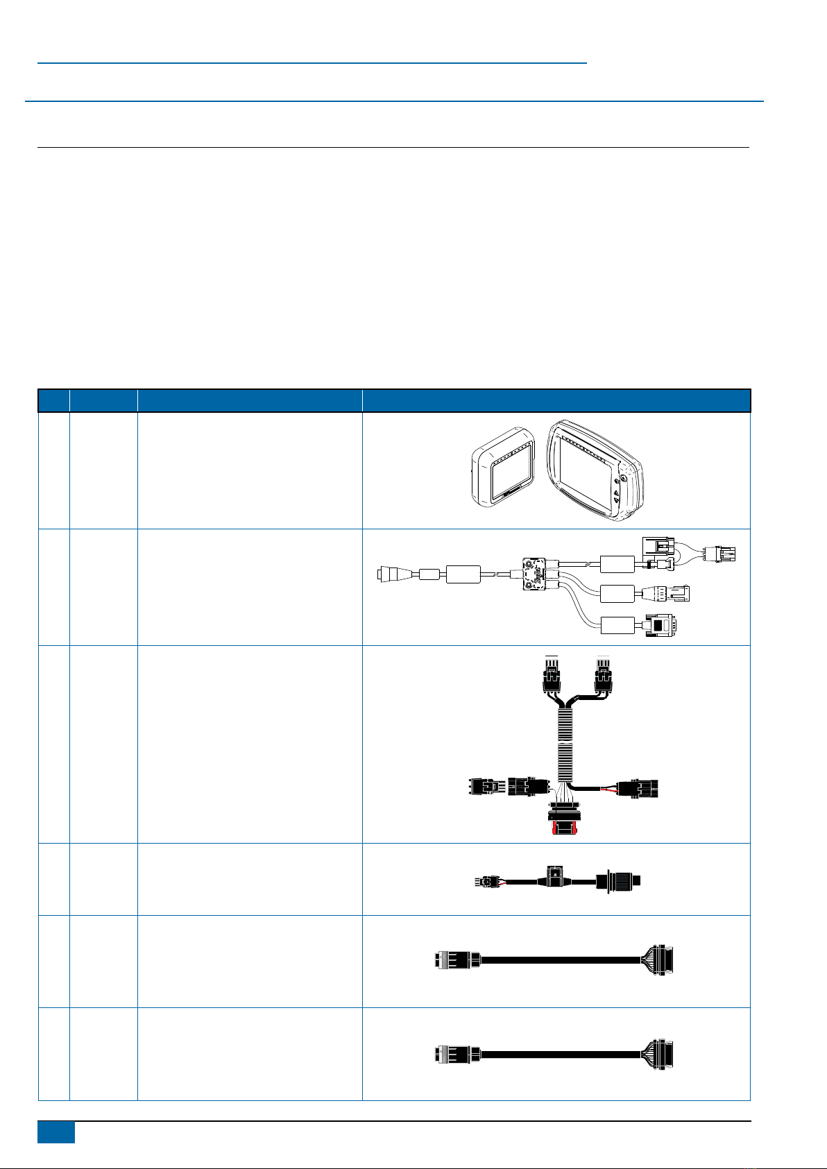
Item Part Number Description Quantity
A 90-xxxxx* Matrix Pro guidance controller kit ....................................................................................................................................1
B 45-05845 Power/CAN/data cable ....................................................................................................................................................1
C 198-410 BoomPilot harness (CANBUS & Power)..........................................................................................................................1
D 48-XXXXX Power cable with 3P COBO connector............................................................................................................................1
E 990-888* BoomPilot cable , 990-888 (Max. 15 Sections + Master for New Sa or Pneumatic Valves) ...........................................1
E 990-889* BoomPilot cable , 990-889 (Max. 15 Sections + Master for Old Sa or ARAG Valves)....................................................1
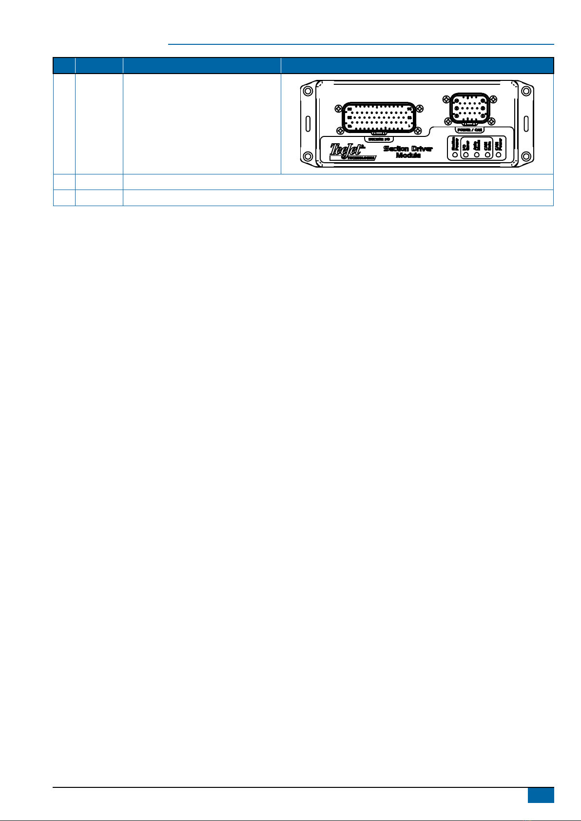
F 78-05072 BoomPilot section driver module (SDM)..........................................................................................................................1
G 020-049 Installation manual, Berthoud TELEVOLUX ....................................................................................................................1
H 98-05243 Matrix Pro BoomPilot setup guide ...................................................................................................................................1
*Part number is dependent on kit contents
Item Part # Description Illustration
A
Part
number is
dependent
on kit
contents
Matrix Pro guidance controller kit Matrix Pro 570G Matrix Pro 840G
B 45-05845 Power/CAN/data cable
POWER IN
CAN
RS-232
Power/DATA
45-05626
C 198-410 BoomPilot Harness, TJ844 (9 sections +
master)
B
B
A
A
A B
D 48-XXXXX Power cable with 3P COBO connector
BA
E 990-888*
BoomPilot cable, 990-888 (Max. 15
Sections + Master for New Sa or
Pneumatic Valves)
E 990-889*
BoomPilot cable, 990-889 (Max. 15
Sections + Master for Old Sa or ARAG
Valves)
3
020-049 R1 EN
BoomPilot®
Item Part # Description Illustration
F 78-05072 BoomPilot section driver module (SDM)
G 020-049 Installation manual, Berthoud TELEVOLUX
H 98-05243 Matrix Pro BoomPilot setup guide
4www.teejet.com
BoomPilot®
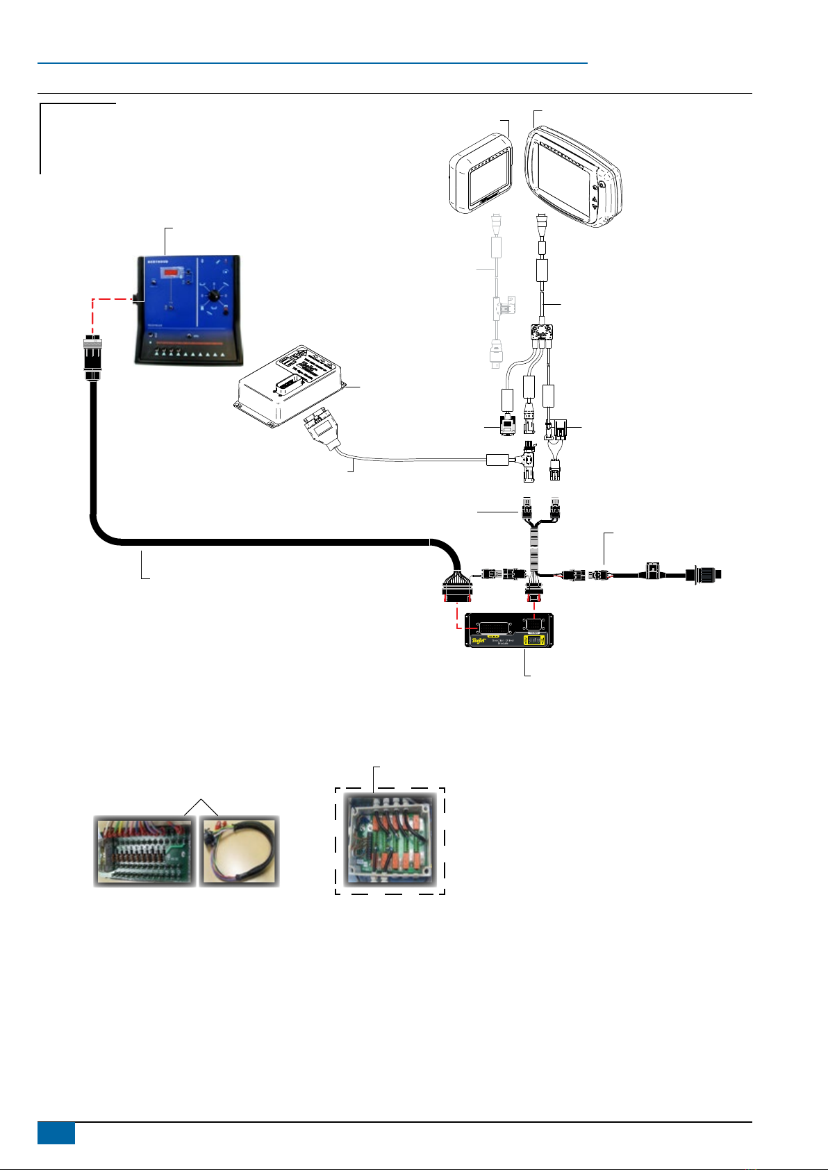
Figure 1: System diagram
POWER IN
CAN
RS-232
Power/DATA
45-05626
45-05845 3.3 m
Power/CAN/data cable
(included with FieldPilot
and BoomPilot kits)
10A fuseto RS-232
CAN
Tilt gyro
module (TGM)
TGM harness
Power
45-05625
45-05625 Power cable, COBO
(included with Matrix Pro kits)
NOT NEEDED WITH BOOMPILOT
B
B
A
A
A B
Section Power
BA
Berthoud TELEVOLUX
BoomPilot cable
Maximum 15 sections + master
990-888: new Safi or Pneumatic valves
990-889: old Safi or ARAG valves
78-05072
BoomPilot Section Driver (SDM)
(15 sections)
45-05648
Power cable with
3 position COBO connector
198-413 BoomPilot harness
(CANBUS & Power)
902-422
Berthoud ABSC Interface
902-356
Relay box
(Only kit no. 990-899 for ‘OLD SAFI’ & ‘ARAG’ valves)
Matrix Pro 570 Matrix Pro 840
Existing system
Not needed
BoomPilot
Optional accessory
5
020-049 R1 EN
BoomPilot®
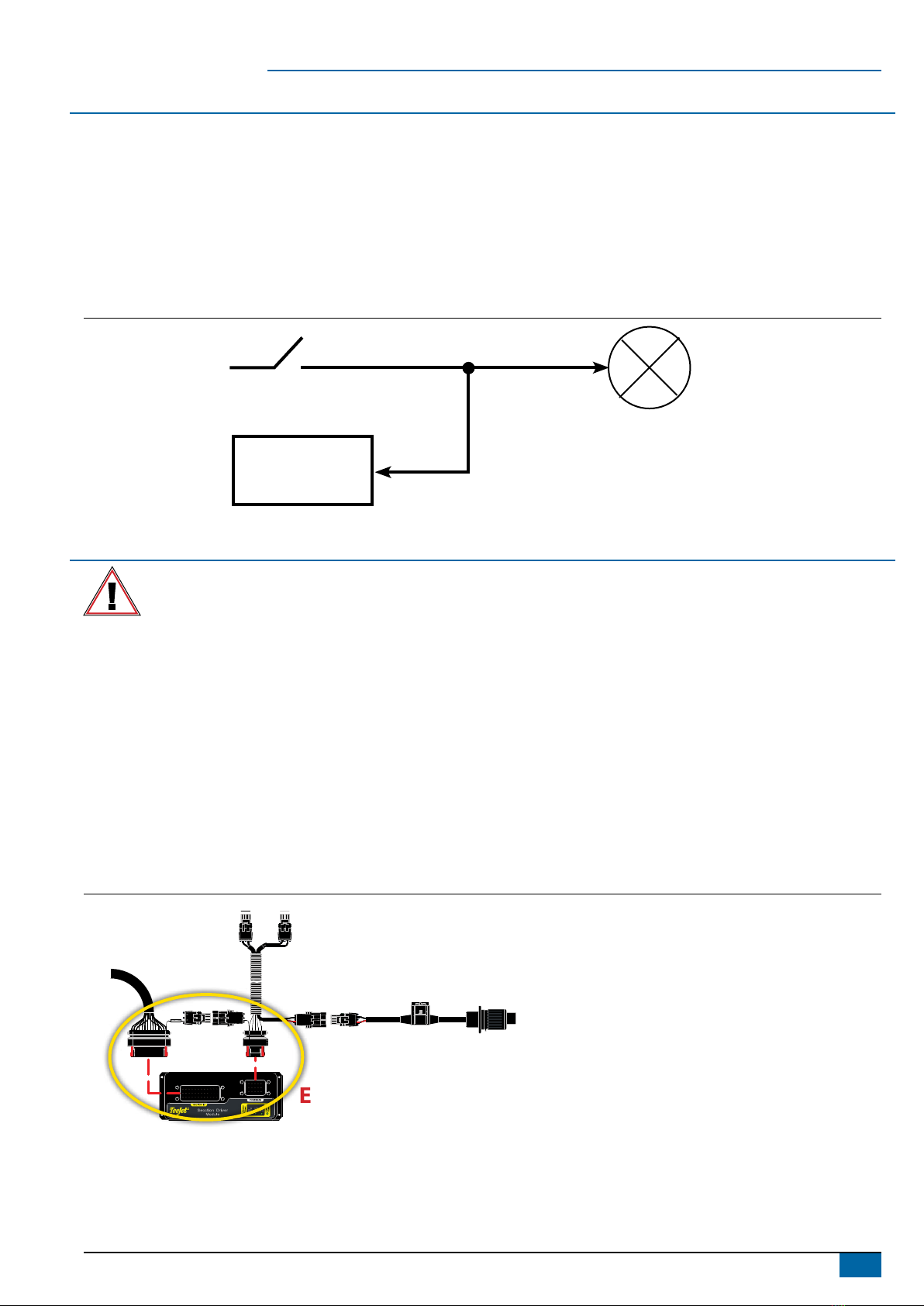
PRINCIPLE OF OPERATION
The BoomPilot system controls the sections valves according to the GPS position. The GPS makes it possible to avoid overlaps or skips.
The Section Driver Module (SDM) is designed for switching active high when spraying. This means that a 12V signal is issued to control the
corresponding section valve.
The SDM is connected in parallel with the controller section switches.
The BoomPilot controls the section valves in automatic mode, and the controller section switches should be set to off unless the operator
wants to override the auto mode and thus force spraying.
The BoomPilot monitors the controller section switches that controls the valves in manual mode. The the Master switch can be used both in
automatic mode as well as in manual mode.
Figure 2: Principle of operation
SDM
Controller Section Switch
Valve
INSTALLATION
If there are questions concerning the installation of the BoomPilot system on this vehicle, or due to the changes in component
specications the parts supplied in the kit are not exactly as presented in this document, please contact your dealer or TeeJet
Customer service representative for clarication before installation. TeeJet Technologies is not responsible for misuse or incorrect
installation of the system.
NOTE: All references to left and right are stated as if the user is seated in the driver’s seat.
NOTE: BE VERY CAREFUL TO ABSOLUTELY SECURE ALL CABLES AND HOSES SO THAT THEY DON’T INTERFERE WITH THE MANY
MOVING PARTS OF THE MACHINE!
1. LOCATE THE CONNECTION POINT FOR THE SDM HARNESS
Locate the existing system’s ow control harness on the right side of the cab under the control panel inside the black cowling as it routes up to
the back of the Berthoud TELEVOLUX console.
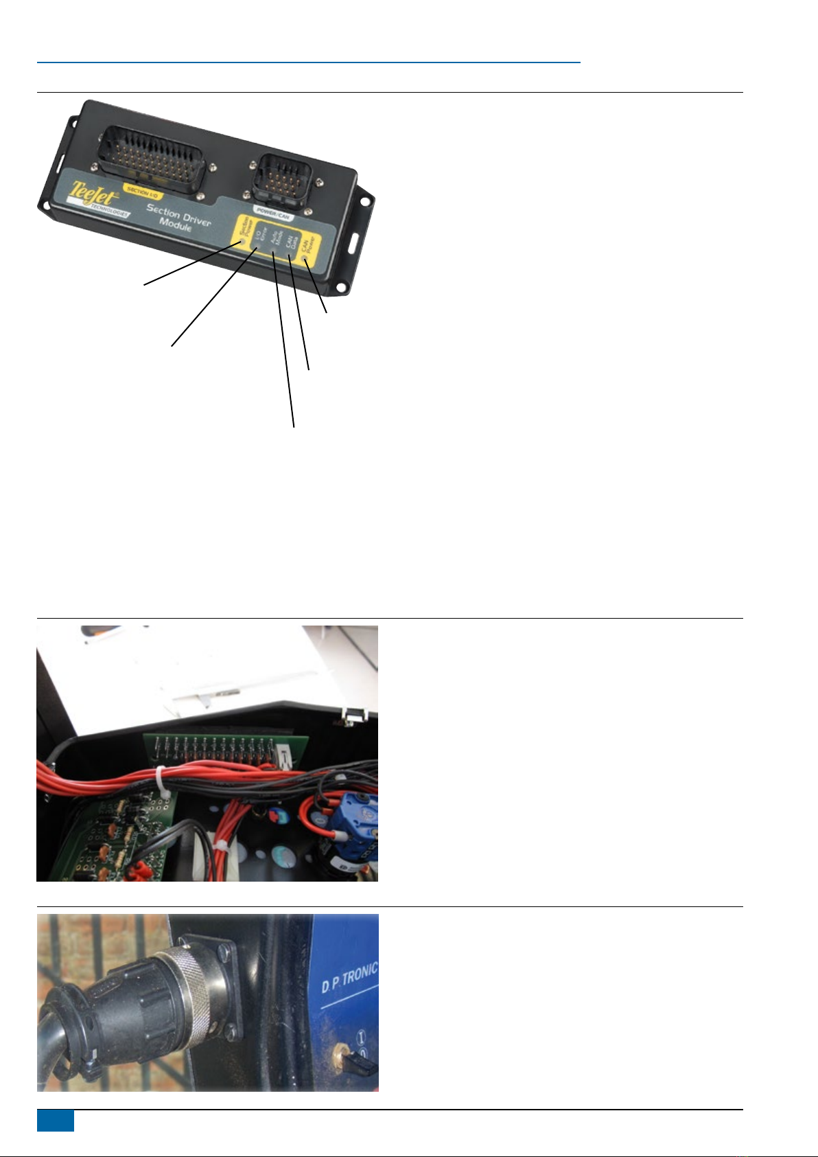
2. MOUNT & CONNECT SDM
1. Mount SDM (E) as shown where LED’s can be seen for troubleshooting.
2. Connect SDM (E) to BoomPilot Harness (C).
Figure 3: Connect SDM
B
B
A
A
A B
Section Power
BA
E
C
6www.teejet.com
BoomPilot®
Figure 4: LED description
Section power
On – boom section power is on
Off – boom section power is off
In/out error
Off – boom output is high or on
Blinking – boom output is low or off
Auto mode
On – auto mode is active
Off – manual mode is active
CAN data
Blinking – receiving console CAN messages
Off – CAN messages stop for > 3 seconds
CAN power
On – CAN power is on
Off – CAN power is off
3. INSTALLING THE BERTHOUD TELEVOLUX KIT
To get electrical contact with the Sections and the Master switch in the Berthoud TELEVOLUX Switch Box, it’s necessary to install a Berthoud
ABSC Interface (See pos. 7 and 8 on the two System Overview drawings). Before starting the installation, make sure that the power is
disconnected.
Warning: This is a critical operation and must only be conducted of persons with the necessary skills. In case the Berthoud TELELUX
Switch Box is damaged during the installation, it’s on the buyers sole risk and therefore the buyer is not entitled to any form for
compensation.
Figure 5: Installing the Circuit board
Place the interface in the right part of the box as shown on
the picture.
Drill two ø3.5 mm holes in the plastic housing with a
distance of 95 mm.
It’s practical to install the wires on the interface before
installing it (See diagram next page).
Figure 6: Installing the Connector
CenterLine 230BP; Berthoud DP Tronic Installation Manual
020-045-UK R1
Make a hole in the left part of the plastic
housing and install the round connector. The
Hole should be ø25 mm and xing holes ø3.2
mm.
Connect the Automatic Boom section kit
as show on the system overview drawings.
The kit includes all necessary connectors
to get electrical contact with the Berthoud
TELEVOLUX Switch Box.
7
020-049 R1 EN
BoomPilot®
Carte pulve
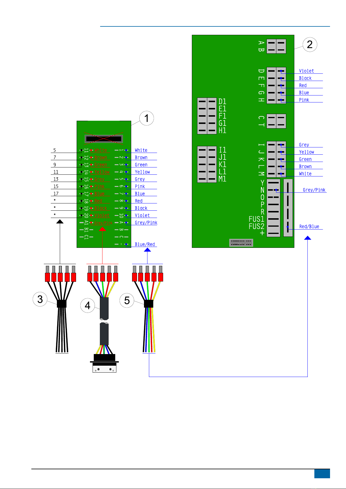
1. Connect the external connector cable (4) to the interface (1), in the middle row.
2. Disconnect the wires (3) from the “Carte Pulvé” board (2) and connect them to the interface (1).
3. Connect the wires (5) to the interface (1) and to the “Carte Pulve” board (2).
8www.teejet.com
BoomPilot®
4. DISCONNECT & RECONNECT HARNESSES & CABLES
The BoomPilot SDM harness (C) tees into the existing system’s connection between the Berthoud TELEVOLUX rate controller and ow
control harness.
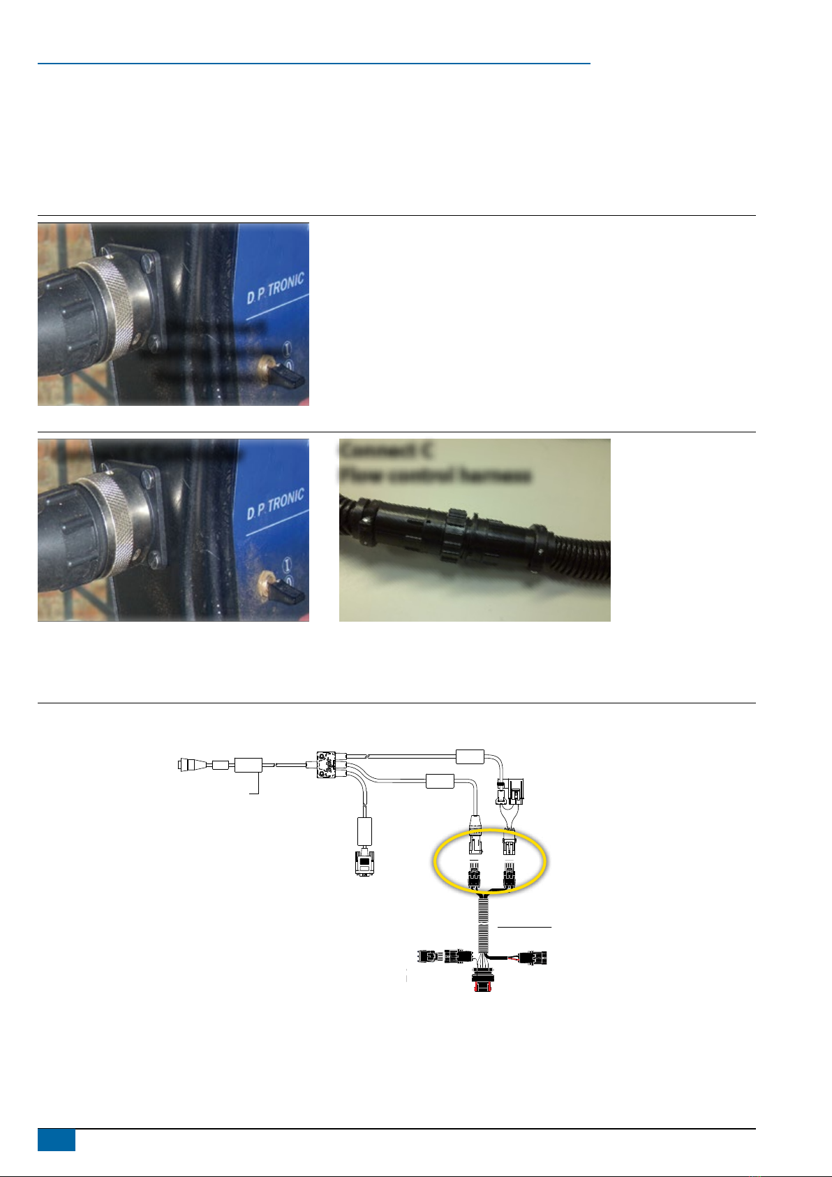
1. Disconnect existing connection at the back of the Berthoud TELEVOLUX console.
2. Connect BoomPilot harness (C) to Berthoud TELEVOLUX console.
3. Connect BoomPilot harness (C) to existing Berthoud TELEVOLUX ow control harness.
Figure 7: Disconnect existing connection
CenterLine 230BP; Berthoud DP Tronic Installation Manual
020-045-UK R1
Disconnect
existing harness
from console
Figure 8: BoomPilot harness to flow control harness BoomPilot harness to controller
CenterLine 230BP; Berthoud DP Tronic Installation Manual
020-045-UK R1
Connect C Controller
Connect C
Flow control harness
5. CONNECT POWER/CAN/DATA CABLE TO BOOMPILOT HARNESS
Connect Power/CAN/data cable (B) to BoomPilot harness (C).
Figure 9: Connect power/CAN/data cable to BoomPilot harness
POWER IN
CAN
RS-232
Power/DATA
45-05626
Power/CAN/Data Cable
BoomPilot harness
(CANBUS & Power)
B
B
A
A
A B
B
C
Altri manuali per TeeJet TECHNOLOGIES BoomPilot
6
Indice
Altri manuali Spraying Systems Sistema di controllo

Spraying Systems
Spraying Systems AutoJet SCS Series Manuale utente

Spraying Systems
Spraying Systems TeeJet 845 Manuale utente

Spraying Systems
Spraying Systems TeeJet TECHNOLOGIES BoomPilot Manuale utente

Spraying Systems
Spraying Systems TeeJet 844-E Manuale utente

Spraying Systems
Spraying Systems 1550+ AutoJet Manuale utente

Spraying Systems
Spraying Systems TeeJet TECHNOLOGIES BoomPilot Manuale utente

Spraying Systems
Spraying Systems TeeJet Technologies 744E Manuale utente

Spraying Systems
Spraying Systems TeeJet TECHNOLOGIES BoomPilot Manuale utente

Spraying Systems
Spraying Systems TeeJet BOOMPILOT Manuale utente


