Tempsens CALsys 1500 BB Manuale utente

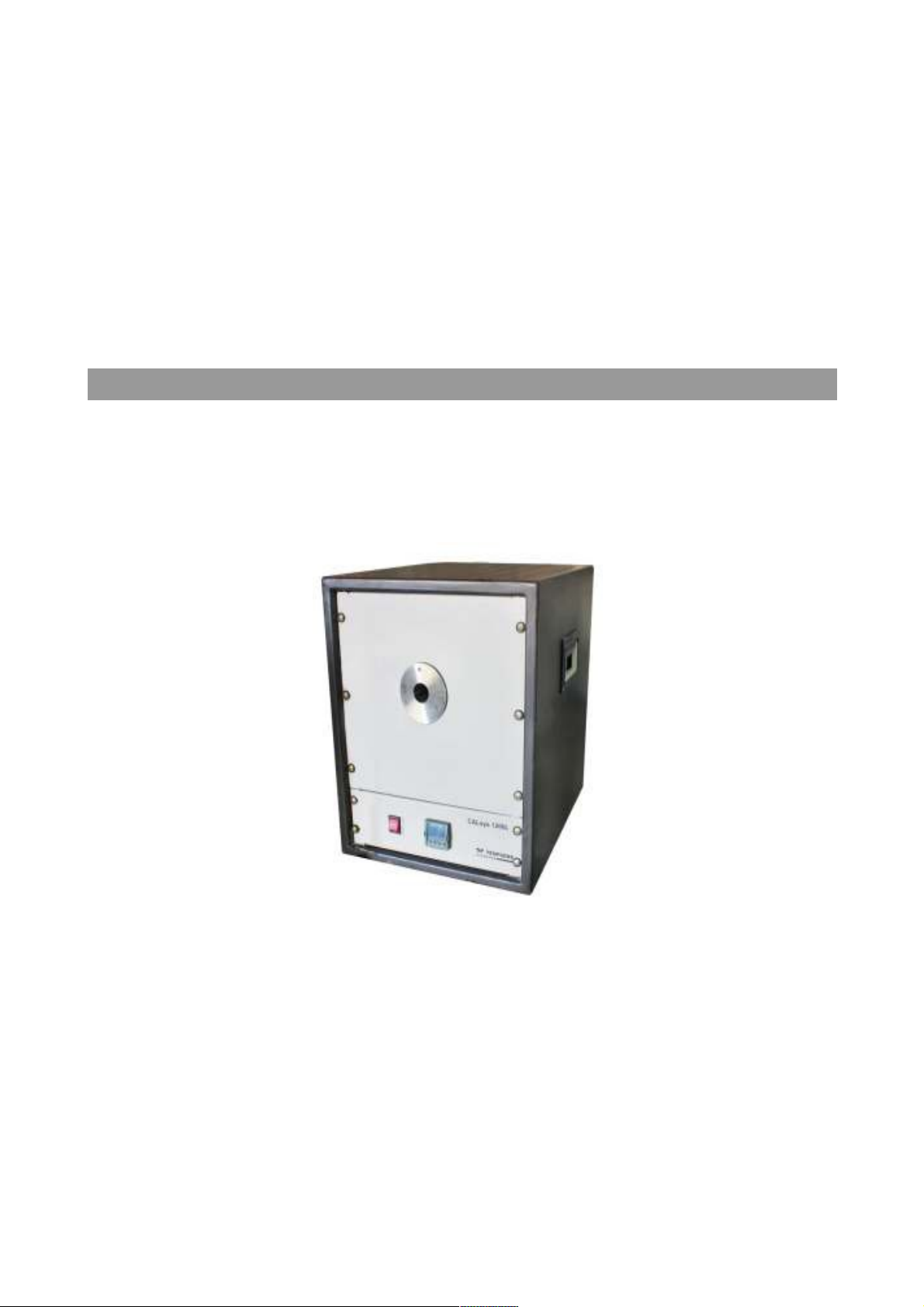
CALsys 1500 BB
CALsys 1500 BB
Black Body Temperature Calibrator
USER MANUAL

CONTENTS
1. General Instruction........................................................................1
1.1 Inform tion on oper ting instruction
1.2 Li bility & w rr nty
1.3 Unp cking & initi l inspection
2Before you start.............................................................................2
2.1 S fety inform tion
2.2 W rning
2.3 C ution
3 Tec nical Data................................................................................3
3.1 Technic l specific tion
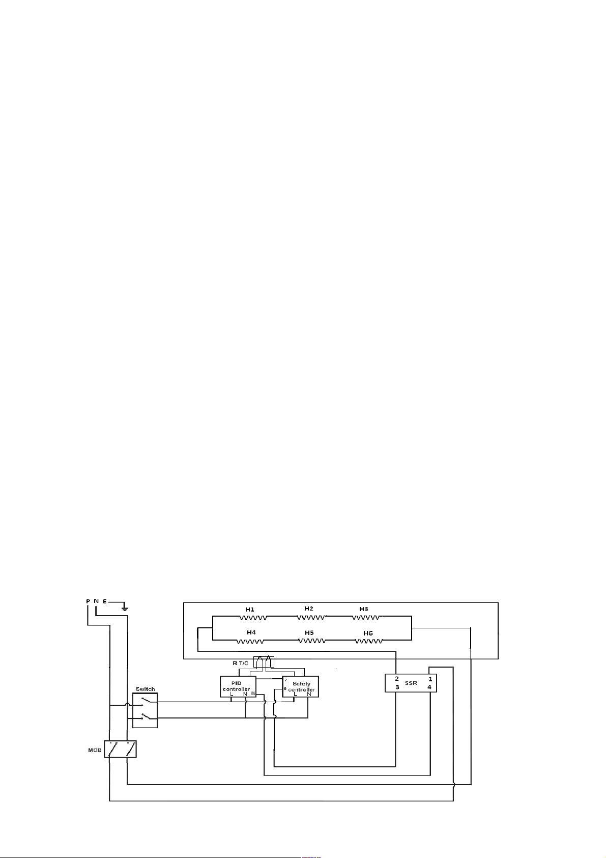
3.2 Circuit di gr m
4 Overview........................................................................................4
4.1 Introduction
4.2 Outline description
5. Operating Instruction.....................................................................5
5.1 Power
5.2 Setting the temper ture
5.3 Oper ting Instruction
6. Operation of Controller...................................................................6
6.1 The Temper ture Controller
6.2 Altering the set point
6.3 Monitoring the Controlling St tus
6.4 Units
7. Maintenance & Trouble s ooting.....................................................7
7.1 M inten nce
7.2 Troubleshooting
8. Software Installation......................................................................8
8.1 Inst ll tion
8.2 P r meter in m in screen

1. Ge eral I structio
1.1 Information on operating instruction
Congr tul tions on your purch se of high-qu lity nd efficient CALsys 1500BB temper ture
c libr tor.Re d this m nu l c refully to ll instructions on s fety, oper tion nd m inten nce. It
serves s n import nt source of inform tion nd reference for inst ll tion nd oper tion of the
device. The gener l s fety requirements must be strictly dhered to when oper ting the
device. The f ct cont ined especi lly s fety re observed. If you experience ny further
questions, ple se cont ct our technic l support by phone or m il to tech@tempsens.com
1.2 Liability and warranty
This instrument h s been m nuf ctured to ex cting st nd rds nd is w rr nted for twelve
months g inst electric l bre kdown or mech nic l f ilure c used through defective m teri l or
workm nship, provided the f ilure is not the result of misuse. In the event of f ilure covered
by this w rr nty, the instrument must be returned, c rri ge p id, to the supplier for
ex min tion nd will be repl ced or rep ired t our option.
INTER F ER E N C E WI T H O R F A I L U R E T O P R O P E R L Y M A I N T A I N T H I S I N S T R U M E N T M A Y
INV AL I D T H I S W A R R A N T Y .
1.3 Unpacking & Initial Inspection
Our p cking dep rtment uses custom designed p ck ging to send out your unit, but s
ccidents c n still h ppen in tr nsit, you re dvised, fter unp cking the unit, to inspect it for
ny sign of d m ge, nd confirm th t your delivery is in ccord nce with the p cking note. If
you find ny d m ge or find ny p rt missing during delivery notify us nd the c rrier
immedi tely. If the unit is d m ged you should keep the p cking for possible insur nce
ssessment.
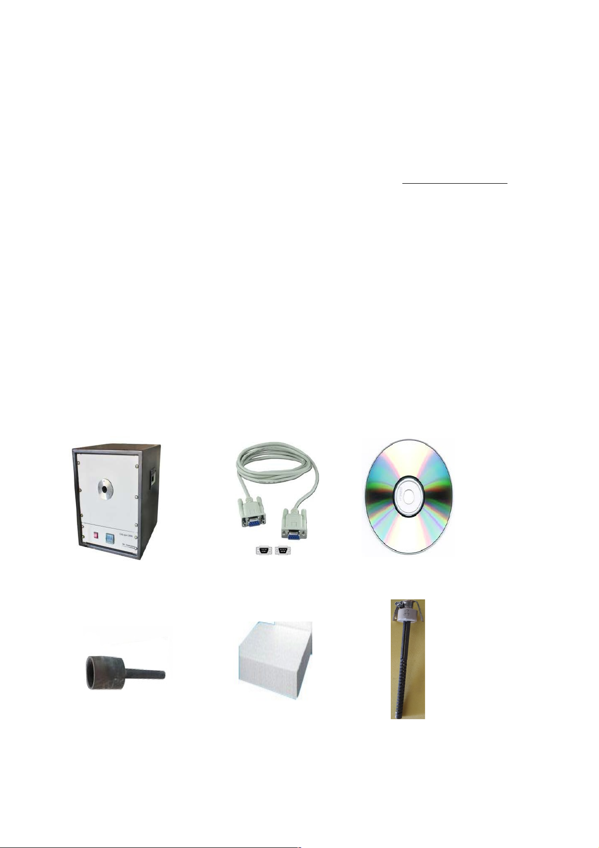
After unp c k in g you will find following items.
C lsys 1500 BB RS- 23 2 c ble Softw re C D
Silicon C r bi de C vity Insul tion wool 6 N OS.He ters

2. Before you Start
2.1 Safety Information
Use the instrument only s specified in this m nu l. Otherwise, the protection provided by the
instrument m y be imp ired. Refer to the s fety inform tion below nd throughout the m nu l.
The following definitions pply to the terms “W rning” nd “C ution”.
“W rning” identifies conditions nd ctions th t m y pose h z rds to the user.
“C u tio n ” i dentifies conditions nd c ti o ns th t m y d m ge the instrument
being used.
[!] Warning: T e furnace is only to be used as described in t is
manual. It is recommended t at you only use accessories provided by
t e manufacturer.
2.2 Warning
To void possible electric shock or person l injury, follow these guidelines.
This equipment must be correctly e rthed.
A protective e rth is used to ensure the conductive p rts c n not become live in the event of
f ilure of the insul tion.
The protective conductor of the flexible m ins c ble which is colored green/yellow MUST be
connected to suit ble e rth.
W rning: Intern l m ins volt ge h z rd. Do not remove the p nels.
There re no user service ble p rts inside. Cont ct us for rep ir.
Do not use the pp r tus outside its recommended r nge i.e., + 500 to 1500° C.
Ensure infl mm ble m teri ls, re kept w y from hot p rts of the pp r tus, to prevent
fire risk.
Before connecting to the electricity supply, ple se f mili rize yourself with the p rts of the
c libr tor with the help of oper ting m nu l.
BURN HAZARD – Do not touch the t rget surf ce of the unit.
Alw ys repl ce the fuse with one of the s me r ting, volt ge nd type.
Overhe d cle r nce is required. Do not pl ce unit under c binet or other structure.
Do not use this unit for ny pplic tion other th n c libr tion work.
Completely un ttended high te m pe r t u r e oper tion is no t r e c o mmended for
s fety re sons.
CALIBRAT ION EQUIPEMENT should only be used by TRAINED PERSONNEL.
We r ppropri te protective clothing.
2.3 Caution
To void possible d m ge to the instrument, follow these guidelines.

Components nd he ter lifetime c n be shortened by continuous high temper ture
oper tion.
Do not c h nge the v lues o f the c li br tion const nts fr o m the f c tory se t
v lues. The co rr e c t setting of the s e p r me te r s is import nt to the s f e t y
nd proper o per tio n o f the c l i br tor.
3. Tech ical Data
3.1 Tec nical Specification
Volt ge 230 V AC
Power M ximum
Supply Frequency 50/60 Hz
Temper ture r nge 500 to 1500°C
Resolution 1.0 °C
St bility ± 1.0 °C
Controlling sensor R type T/C
Time to re ch m x. Temper ture 2.5 hours
Oper ting Temper ture 20 to 45 °C
Controller Specific tions Eurotherm 3216 Series
Over temper ture protection Autonics controller with R Type T/C
St biliz tion Time 15 to 20 Min.
Dimensions 590(H) x 450(W) x 530(D) mm
R di tion c vity type & Dimension Silicon Carbide,46 mm Dia x 85mm depth
Extern l Aperture 40 MM
Weight Approx 50 kg
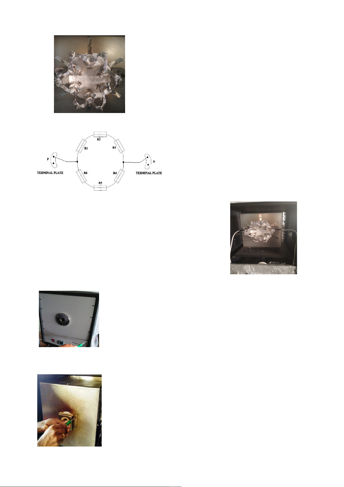
3.2Circuit Diagram

P: PHASE= RED WIRE
N: NEUTRAL = BLACK WIRE
E: EARTH =BLUE WIRE
4. Overview
4.1 Introduction:
The ‘CALsys 1500BB’ provides st ble temper ture source for l bor tory c libr tion of
r di tion thermometers by comp rison method up to temper ture r nge of 1500°C.
The ‘CALsys 1500BB’ model h s been designed in single p rt. This model provides n
isotherm l enclosure in which the Non cont ct pyrometers c n be checked g inst the
temper ture of the bl ck body. For tr ce ble c libr tion m ster pyrometer should be used.
The units’ fe tures emissivity of 0.99, thus offering the closest pproxim tion of t rget
surf ce th t is perfect emitter of infr red energy.
The ‘CALsys’ models re p rt of wide r nge of c libr tors designed nd m de by us. Ple se
cont ct us in c se you require more inform tion bout our other pro-ducts.
DANGER! Power is present even if t e front panel circuit breaker is in t e OFF (0)
position.
4.2 Outline Description:
‘C lsys 1500BB is tr nsport ble unit designed for use on ny re son ble fl t surf ce. The
t rget is ridged luminum pl te which is p inted by high emissive p int .The t rget is
he ted by Silicon Carbide Spiral Rod Heater which llows the source to he t up to 1500°C in
bout 2.5 Hrs nd hold it st ble t temper ture within ±1.0°C. The he ter blockhouses consists
he ter & the controller sensor. The temper ture controller to sense the block temper ture
uses this sensor. To obt in the m int in required temper ture the controller v ries the power
to the he ters vi solid-st te rel y.
[!]Warning: Do not insert impure materials, metal objects or probes etc. into t e
block.
4.3 INSTALLATION OF CALSYS 1500BB
Unpack t e furnace carefully and inspect it for any
damage t at may ave occurred during s ipment.
If t ere is s ipping damage, notify t e carrier
immediately.

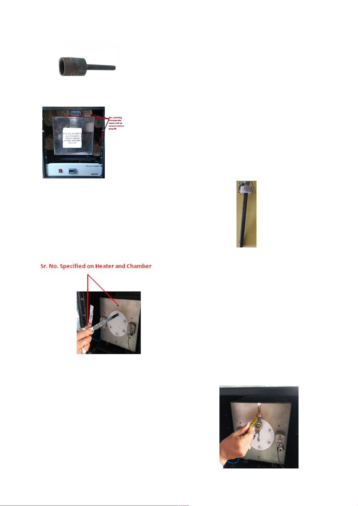
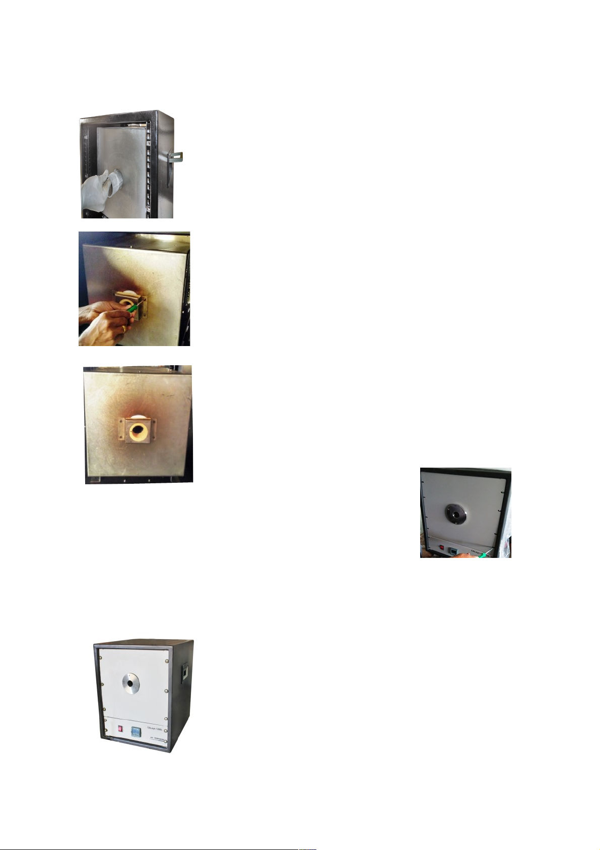
Silicon Carbide Cavity
Insert the he ters in to the groves of SS ch mber s
per specified s me sr. no. On he ter holder nd
ch mber.
NOTE: HEATERS INSERT VERY CAREFULLY.
After Inserting its tig t by screwdriver
Open b ck p nel sheet of CALsys 1500 nd
remove all Packing s eet from inside.
Insert t e 6 nos. silicon eater at back side
of t e inner c amber. As s own in below
image.

connect t e P ase and Netural wire as per given picture.
Ope holdi g ceramic clamp as show i figure.
Ope the fro t plate of CALsys 1500BB a d remove
all packi g sheets from i side.
Fix t e 6 eater into t e c amber and
Connect all t e aluminum strip in
series.
Heating Element connection.

fix t e front plate of calsys 1500BB
Fully assembled of CALsys 1500BB
I sert cavity a d e sure that the tail of cavity fix to the
groove o the back pa el.
A d make sure cavity properly i sert at back pa el hole
as show i image.
After insert the cavity tight the holding cap of SS
chamber by screw driver as per shown picture.
After completed holding clamp its look like this.

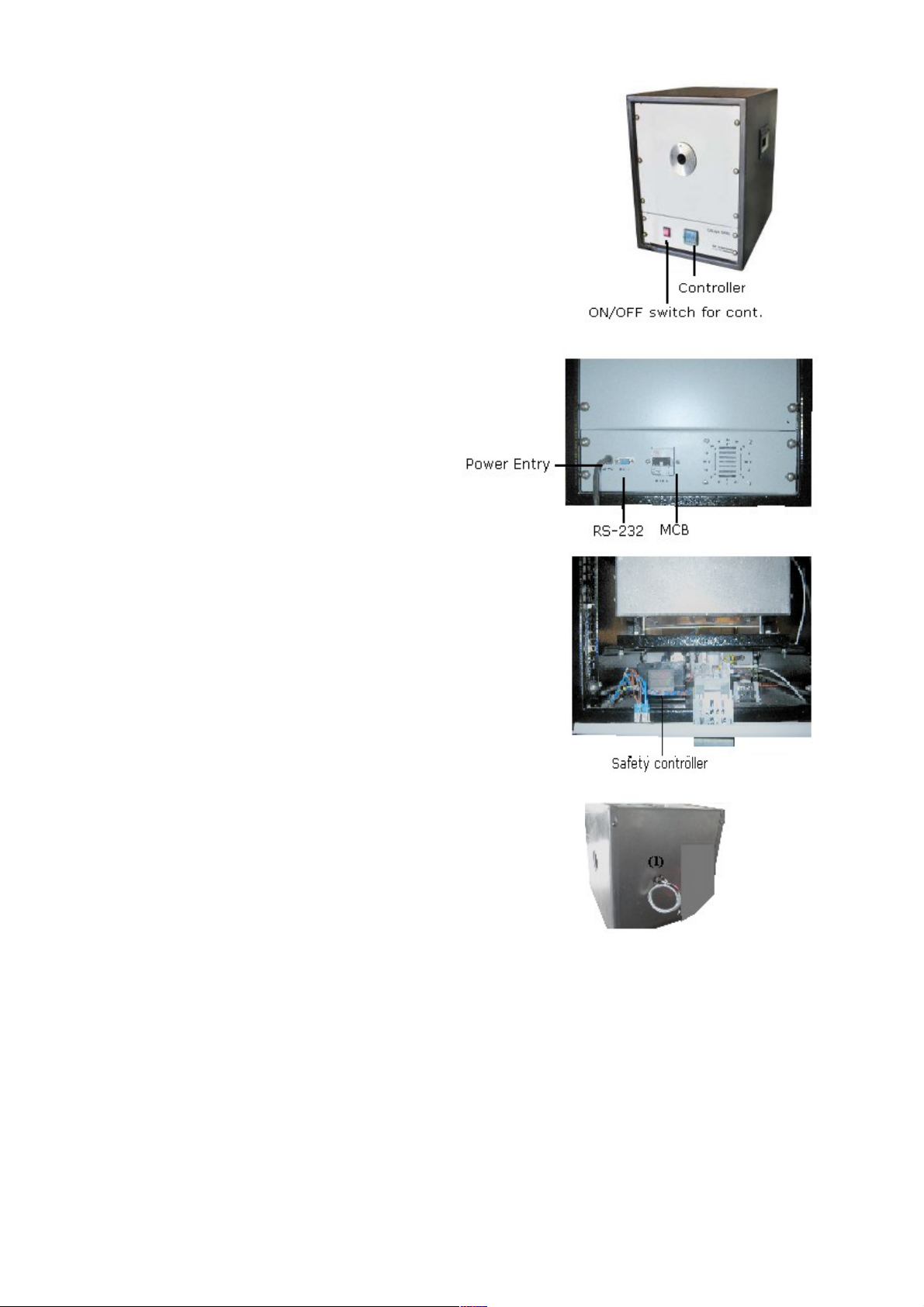
5. Operati g I structio
(1) PID Controller
(2) ON/OFF switch of controller
(3) Power C ble
(4) RS-232
(5) MCB (for He ter)
(6) S fety controller for over he ting temper ture.
(7) 1."R" type thermocouple Duplex for controlling nd
over temper ture protection.
Inner ch mber of c lsys 1500BB
5.1 Power
Plug the bl ck body power cord into m ins outlet of the proper volt ge, frequency nd current
c p bility. Typic lly this will be (230 VAC±10%, 50-60 Hz). Turn on the bl ck body using "M ins"
switch lo c ted t re r side. The bl ck body will turn on nd begin to he t for previously
progr mmed set point.
5.2 Setting t e Temperature Press “UP” or “DOWN” buttons to ch nge the ch nge the
temper ture set-point v lue. When the set-point temper ture is ch nged the controller
Indice
Altri manuali Tempsens Strumento di misura

Tempsens
Tempsens CALsys 1700 Manuale utente

Tempsens
Tempsens CALsys 1500 Manuale utente

Tempsens
Tempsens CALsys-15/110 Autocal Manuale utente

Tempsens
Tempsens CALsys 1200 Manuale utente

Tempsens
Tempsens CALsys 1500 L Manuale utente

Tempsens
Tempsens CALSYS 650 Manuale utente

Tempsens
Tempsens CALsys 250 Manuale utente

Tempsens
Tempsens CALsys -35/200 Manuale utente